
Method for laser-induced thermal separation of plate glass

a technology of plate glass and thermal separation, which is applied in the field of low-damage separation of flat glass sheets, can solve the problems of inefficiency with regard to a higher cutting speed, limited cutting speed by increasing the applied laser energy, and long pauses

Inactive Publication Date: 2007-07-05
FRAUNHOFER GESELLSCHAFT ZUR FOERDERUNG DER ANGEWANDTEN FORSCHUNG EV +1
View PDF8 Cites 70 Cited by
  • Summary
  • Abstract
  • Description
  • Claims
  • Application Information

AI Technical Summary

Benefits of technology

[0012] In order to make it possible to input more heat into an area element without causing damage, the heat must be applied repeatedly with appropriate pauses. During the pauses, the radiation energy absorbed at the surface can be at least partially conducted into the interior of the material and distributed therein. In this way, the surface temperature is substantially reduced as apparent from theoretical considerations. The accurate length of the needed pauses depends on the type of glass and also the temperature of the glass reached at the surface thereof. For float glass, the experiments performed therewith indicate that, with maximum energy application corresponding to the upper limit value of 0.016 watt×seconds / mm2, a pause of only about 50 milliseconds is very efficient. Longer pauses are possible but inefficient with regard to a higher cutting speed, shorter pauses require a reduced energy input in comparison with the upper limit value in order to avoid the damages described. For a technical application, this means that the heat input must be repetitive and very fast. For the technical implementation of the desired rapid movement of the laser beam spot, scan systems may be used which are capable of realizing scan speeds in the area of over 100 m / s. Furthermore, the computer-based control of the scan systems have the advantage that any desired curves can be produced permitting the cutting of any desired format.
[0016] Instead of applying only a single heat track, several heat tracks (line packet) can be employed which extend parallel or which, respectively, are in close vicinity and preferably symmetrically with respect to the desired separation line. It is to be noted in this connection that a greater width of the line package then 12 to 15 mm will hardly result in a further increase of the stresses. It is however advantageous to work with an uneven number of lines in the package in such a way that one line follows exactly the desired separation line and furthermore to provide for a scanning cycle (the order of scanning) of the lines such that this center is scanned twice in comparison with the other lines. In this way, the center line is given the task of a guide line, which is very important for the cut quality. For a line packet, it is necessary to work with a preheating stretch which is correspondingly shorter in comparison with a single line if comparable conditions are desired.
[0017] In order to be able to score longer or continuous separation lines whose length exceeds the length of the heating stretch calculated in this way, each repetition is extended in the direction of the desired line to be scored by an advancement increment Δx. The incremental length Δx is derived from the desired cutting speed v and the number of the repetitions N. This applies to the steady state, that is continuous, operation. At the beginning and at the end of a cut, it is more advantageous to provide for a stepped heating in such a form that these stretches are subjected to the same heat-up conditions as those under steady state operation.

Problems solved by technology

An increase of the cutting speed by increasing the applied laser energy is limited by the formation of transverse fractures and melting.
Longer pauses are possible but inefficient with regard to a higher cutting speed, shorter pauses require a reduced energy input in comparison with the upper limit value in order to avoid the damages described.
For a technical application, this means that the heat input must be repetitive and very fast.

Method used


Image

  • Method for laser-induced thermal separation of plate glass
  • Method for laser-induced thermal separation of plate glass
  • Method for laser-induced thermal separation of plate glass

Examples


Embodiment Construction

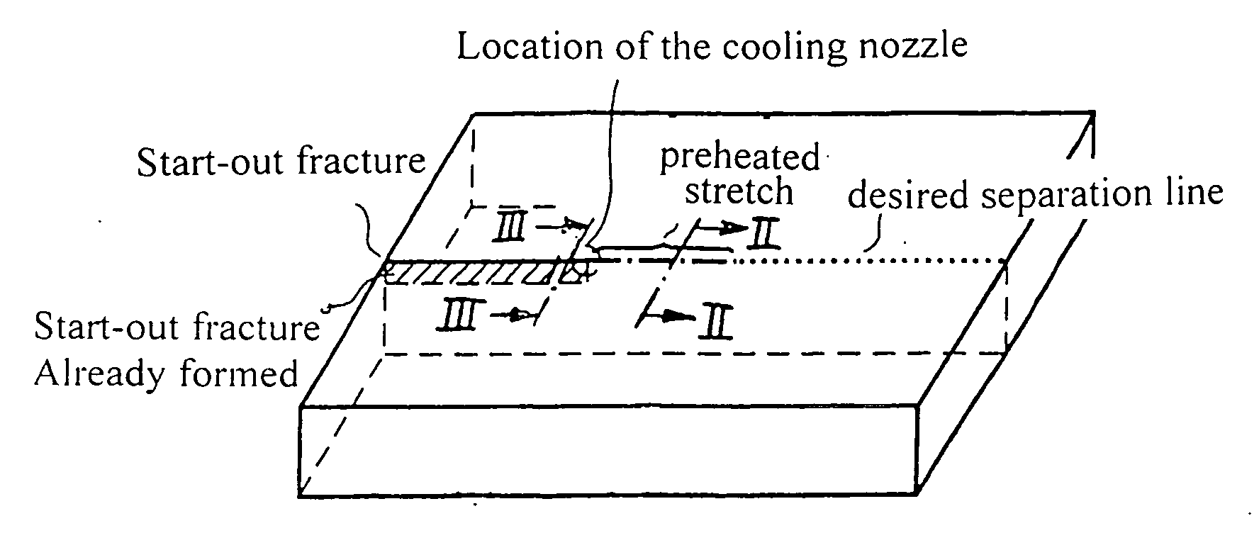
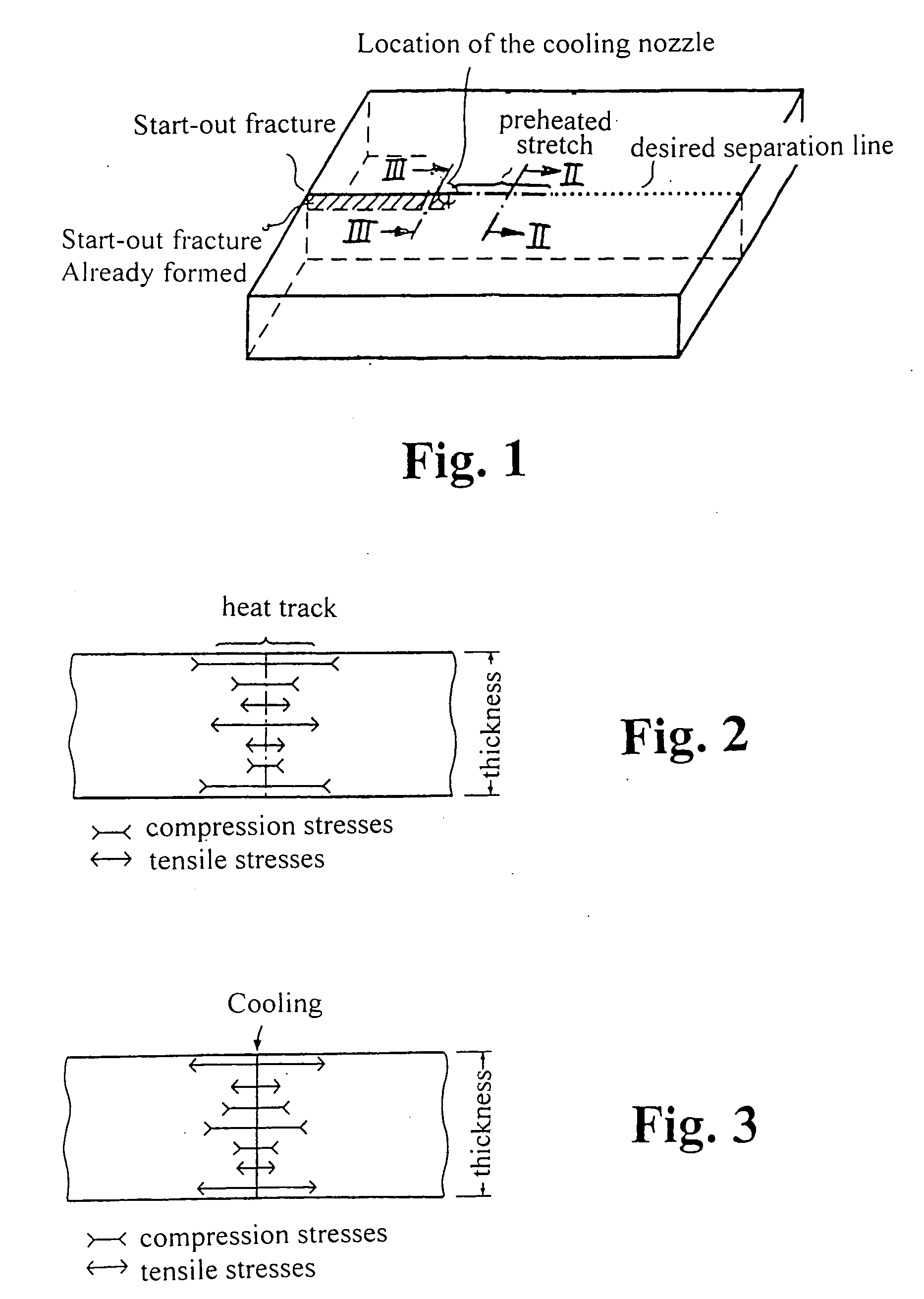
[0030]FIG. 1 shows schematically in a perspective representation a glass plate on which a score is formed along a desired separation line by the method according to the invention. The desired separation line is shown by a dotted line, the location of the start-out score (mechanical damage at the start-out score point) is indicated, the heating stretch, which has been repetitively scanned by the laser beam, is indicated by a dash-dotted line, the cooling nozzle disposed behind the heating stretch is indicated. The start-out crack already formed in the glass (in the area of the stretch already passed by the cooling nozzle) is shown hatched.

[0031] The FIGS. 2 and 3 show the stress conditions in the glass cross-section in the area of the desired separation line at the heating stretch (FIG. 2) in the area of cooling by the cooling nozzle (FIG. 3). The location and the extent of the compressive stresses and the tensile stresses is indicated over the thickness of the glass. Viewed over th...


PUM

PropertyMeasurementUnit
Timeaaaaaaaaaa
Lengthaaaaaaaaaa
Lengthaaaaaaaaaa

Abstract

In a method for a laser-induced thermal separation of plate glass by thermal scoring using a laser beam heating the glass along a desired separation line with subsequent cooling of the laser-heated line, wherein the heat is applied by the laser beam in a number of repetitive passes at intensities based on glass thickness and desired cutting speeds.

Description

[0001] This is a Continuation-In-Part Application of International PCT / DE2005 / 000509 filed Mar. 18, 2005 and claiming the priority of German application 10 2004 014 277.7 filed Mar. 22, 2004.BACKGROUND OF THE INVENTION [0002] The invention relates to a low-damage separation of flat glass sheets wherein a laser is used for a thermal scoring of the glass sheets. [0003] Flat glass sheets are separated still today by scoring with a score wheel and subsequent bending breakage. The required mechanical damaging of the glass surface over the full length of the desired separation line by the score wheel results in the formation of recesses and chips of the glass along the edge thereof which results in a reduced edge strength. Glass chips and the use of cutting oil furthermore can be inconvenient for subsequent treatment procedures such as coating so that the edge area must subsequently be treated by expensive, time-consuming processes such as edging, grinding and washing. [0004] As is well k...

Claims


Application Information

Patent Timeline
IPC IPC(8): B23K26/38B23K26/40C03B33/09
CPCC03B33/091B23K26/4075B23K26/40B23K2103/50Y10T225/12
Inventor DOLL, WALTERKOLLOFF, RAINERKORDISCH, HORSTKUBLER, RAINERSPIESS, GERDFRIEDL, WOLFGANGGLASER, SIEGFRIEDPOHLER, MANFRED
Owner FRAUNHOFER GESELLSCHAFT ZUR FOERDERUNG DER ANGEWANDTEN FORSCHUNG EV
Learn More