Brazeless connector for fluid transfer assemblies

a fluid transfer assembly, brazeless technology, applied in the direction of hose connections, non-disconnectible pipe joints, pipe joints, etc., can solve the problems of difficult permanent leak-tight seal, high temperature, general adverse effects, etc., and achieve good leak-tightness

Inactive Publication Date: 2007-07-05
FLUID ROUTING SOLUTIONS
View PDF46 Cites 20 Cited by
  • Summary
  • Abstract
  • Description
  • Claims
  • Application Information

AI Technical Summary

Benefits of technology

[0011] In one embodiment of the present invention, a metal fitting pre-coated with a thin metallic coating such as zinc-nickel or zinc-cobalt is provided with one or more concentric annular metal barbs on the outer diameter of the metal fitting. The metal fitting is then loosely inserted into the end of the metal tube where the fitting is joined to the tube in a fluid-tight seal created by crimping, swaging, rolling or other means of permanently deforming the metal tube uniformly around the metal barbed fitting. The fluid-tight seal is created by the high pressure of the metal annular barbs pressed against the inner diameter of the metal tube, wherein the inner surface of the pre-coated metallic tube is permanently deformed corresponding to the configuration of the metal annular barbs on the metallic filling. The sealing is further enhanced by the permanent deformation of the inner diameter of the metal tube as it molds itself around the metal barbs, providing an intimate surface- to- surface relationship created between the two surfaces. In this respect, it is important that both the metal tube and the metal barbs on the fitting exhibit similar hardness and thermal expansion rate characteristics in order to create a leak free seal. Similar characteristics allow for the materials to flow and fill any voids or leak paths which may tend to form. The similar metallic materials also provide good leak resistance with respect to temperature and pressure variations.

Problems solved by technology

However, it is difficult to make a permanent leak-tight seal, because the tube, even though malleable, tends to have sufficient elasticity to relax somewhat and deform, upon release of the clamping or crimping pressure just enough to compromise the fluid-tight seal, particularly, when the fluid is under high pressure for an extended period of time.
Conventional connectors are not able to achieve the required tolerances or the strength required to prevent such leaks, Typically, these connectors are brazed or welded to the fluid transfer tubing.
When an assembly is brazed, it undergoes high temperatures which are generally detrimental to any coating or plating on the assembly or on the tubing.
Such methods are generally not desirable because the coating often flakes during bending which leads to high scrap rates.
However, this type of assembly is susceptible to “end play” of the fitting which leads to failure of the seal.

Method used


Image

  • Brazeless connector for fluid transfer assemblies
  • Brazeless connector for fluid transfer assemblies
  • Brazeless connector for fluid transfer assemblies

Examples


first embodiment

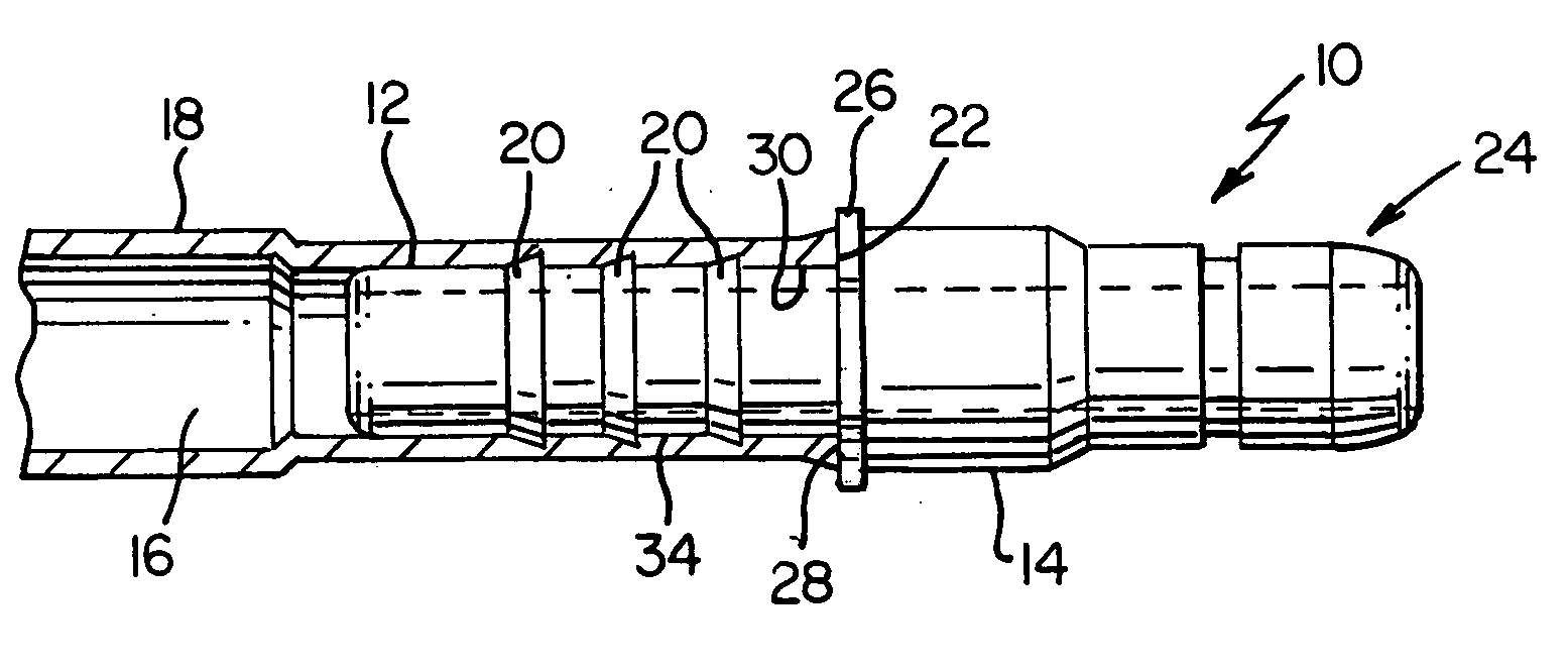
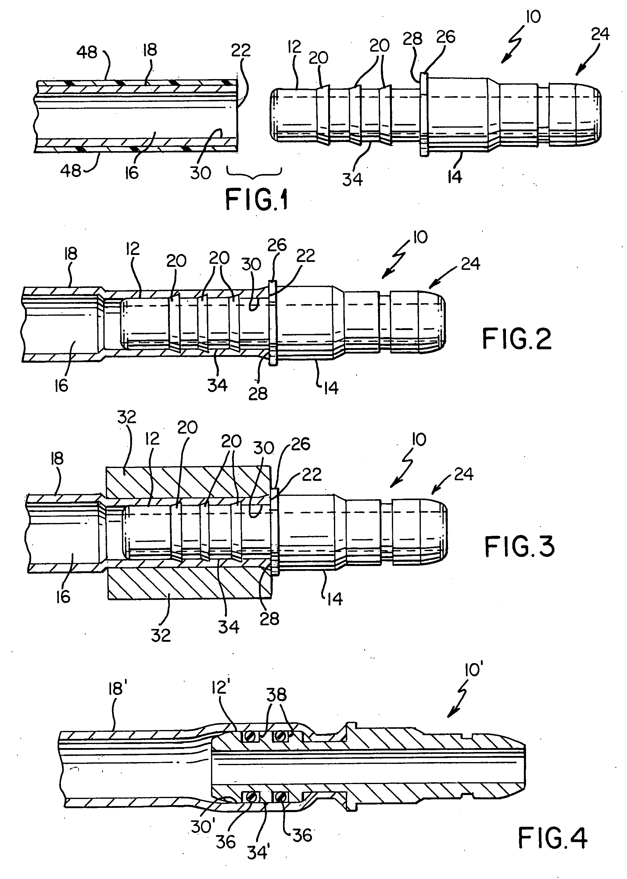
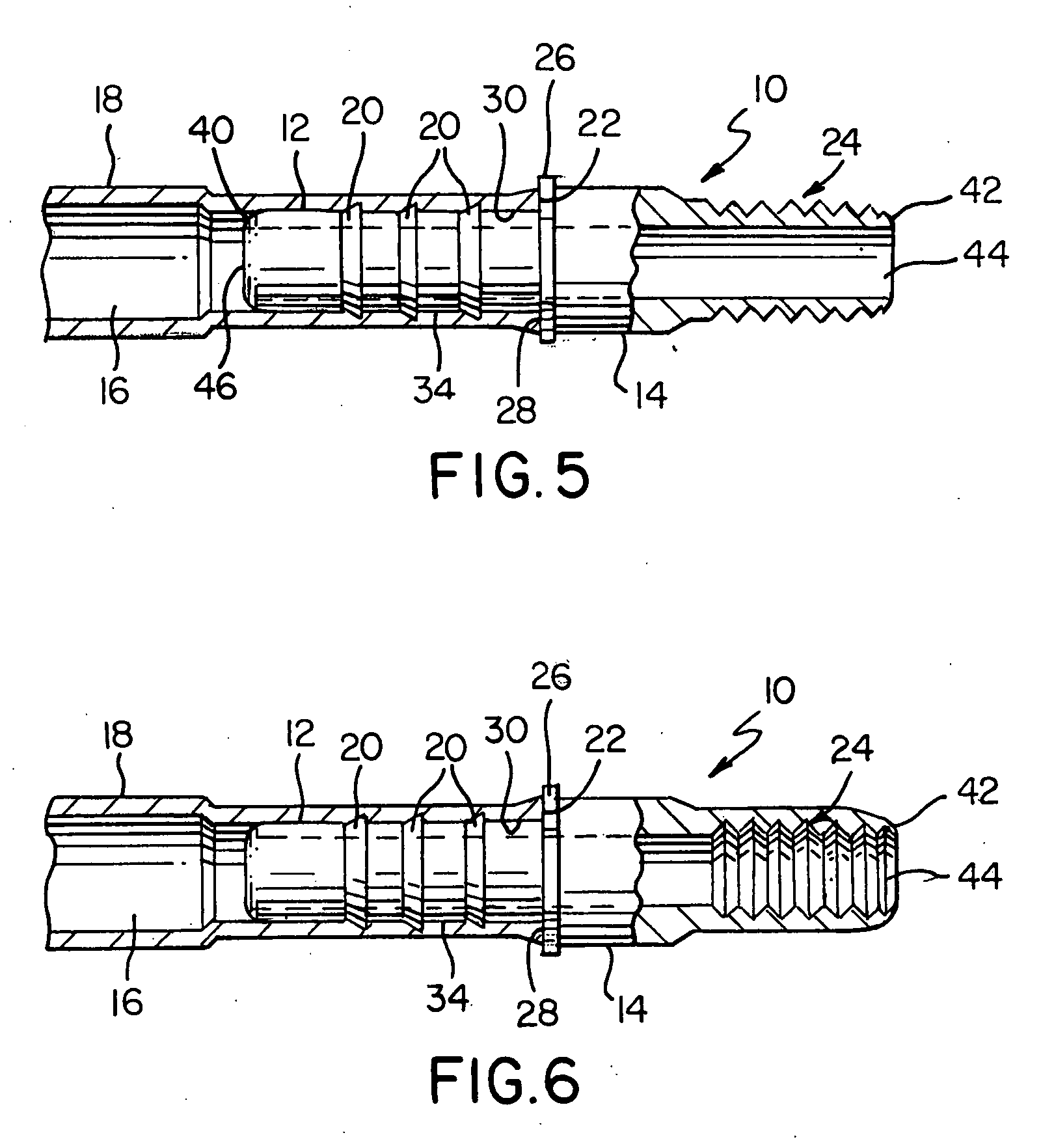
[0019] As illustrated in FIGS. 1 and 2, the metal end fitting 10 of the present invention includes a stem portion 12 defining one end of the end fitting 10 and a coupling portion 14 defining another end of the end fitting 10. The stem portion 12 is adapted to be inserted into an end 22 of an inner channel 16 of a metal tubular structure 18 and secured thereto to provide a leak-free fitting.

[0020] The stem portion 12 includes an annular rim 40 defining an annular opening 46, and one or more annular serrations or barbs 20 circumferentially disposed around the outer circumference of the stem portion 12. The stem portion 12 containing the serrations or barbs 20 is loosely inserted into the end 22 of the metal tubular structure 18 and subjected to crimping, swaging, rolling or other method of permanently deforming the metal tubing 18 uniformly onto the stem portion 12. The leak-free seal is created by the high pressure exerted upon the metal tubular structure 18 wherein the annular serra...

second embodiment

[0028] When the stem portion 12′ is inserted into an open end of a metal tubular structure 18′ and then subjected to high pressure means to clamp the metal tubular structure 18′ around the stem 12′, the resilient O-rings 36′ are compressed to form an intimate contact with the inner surface 44′ of the tubular structure 18′ as well as the annular trough 32′ providing a leak-free seal therein. This second embodiment of the invention allows one to use materials for the metal connector and the metal tubular structure which are not required to be similar in hardness or in thermal expansion rate. For example, in this embodiment the metal connector may be made of steel and the metal tubular structure may be aluminum.


PUM

PropertyMeasurementUnit
circumferenceaaaaaaaaaa
surface areaaaaaaaaaaa
temperatureaaaaaaaaaa

Abstract

A metal end fitting connector having an axial bore through which a fluid is conveyed; comprises a metal stem portion which includes a first metal tubular body having a first annular rim disposed at a distal end of the first metal tubular body, wherein the distal end is adapted to be inserted into an inner channel of a metal fluid transport tube. The metal stem portion includes at least one annular sealing member extending circumferentially outward from an outer surface of the first metal tubular body; and a metal connector portion opposite the distal end of the first metal tubular body. The metal connector portion includes a second metal tubular body having a second annular rim disposed at a distal end of the second metal tubular body, wherein the distal end of the second metal tubular body is adapted to be coupled with another fluid conveying structure.

Description

[0001] This application is continuation-in-part of U.S. patent application Ser. No. 11 / 331,295, filed Jan. 12, 2006, which is a division of U.S. patent application Ser. No. 10 / 170,749, filed Jun. 13, 2002, now abandoned.BACKGROUND OF THE INVENTION [0002] The present invention relates to a coupling device for tubing connections and method for connecting tubes using such coupling devices. More specifically, the present invention relates to the connection of a metal fluid transfer tubing to other metallic connections without having to braze or weld the two pieces together. [0003] Hose coupling devices are known. For example, U.S. Pat No. 3,653,692 to Henson describes an elastomeric hose connected to a nipple having a circumferential barb. The hose is stretched allowing a ring member to slide down the hose and over the barbed nipple where it creates a compression of the hose when the hose is no longer stretched. U.S. Pat. No. 3,477,750 to Powell discloses a pipe section joined by a slee...

Claims


Application Information

Patent Timeline
Patent Type & Authority Applications(United States)
IPC IPC(8): F16L33/00
CPCF16L13/143F16L13/141
Inventor CLEVELAND, RAFAEL L.SKIBA, TERRENCE E.LEMASTER, HERBERT R.
Owner FLUID ROUTING SOLUTIONS
Why Eureka
Try Eureka