
Transmitting/receiving device and communication system using the same

Inactive Publication Date: 2007-07-05
RENESAS ELECTRONICS CORP
View PDF19 Cites 20 Cited by
  • Summary
  • Abstract
  • Description
  • Claims
  • Application Information

AI Technical Summary

Benefits of technology

[0023] Therefore, it is an object of the present invention to provide a low-price semiconductor IC device excellent in adaptability and capable of bidirectional communication with a host by using an inexpensive oscillator.
[0024] It is another object of the present invention to provide a low price semiconductor IC device excellent in adaptability and capable of bidirectional communication facilitating the accommodation to high-speed transmission with a strict noise specification.
[0029] According to the present invention, it is possible to provide a semiconductor IC device excellent in adaptability using an inexpensive oscillator as the reference signal generating source.

Problems solved by technology

Therefore, an expensive price of a crystal oscillator (TCXO) used as an externally mounted component is a great burden to many manufacturers.
Especially, because a lot of semiconductor IC devices require highly accurate reference signals to meet enormous demands for high-speed communication or to resolve deterioration in device noises due to delicate operations in semiconductor fabrication, etc., even more expensive crystal oscillators are now employed.

Method used


Image

  • Transmitting/receiving device and communication system using the same
  • Transmitting/receiving device and communication system using the same
  • Transmitting/receiving device and communication system using the same

Examples


embodiment 1

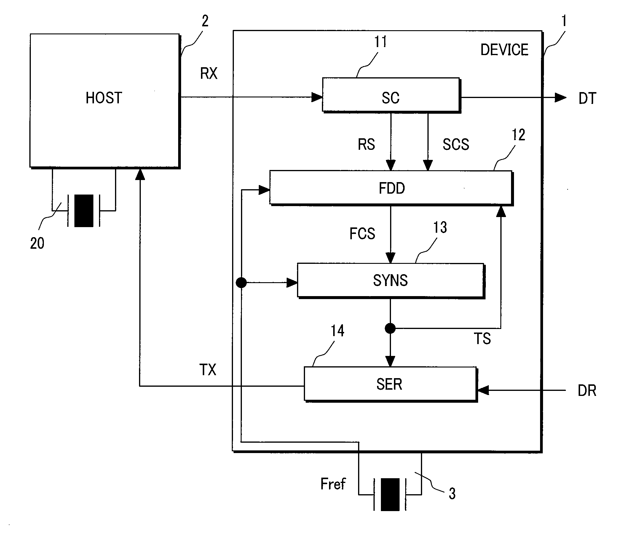
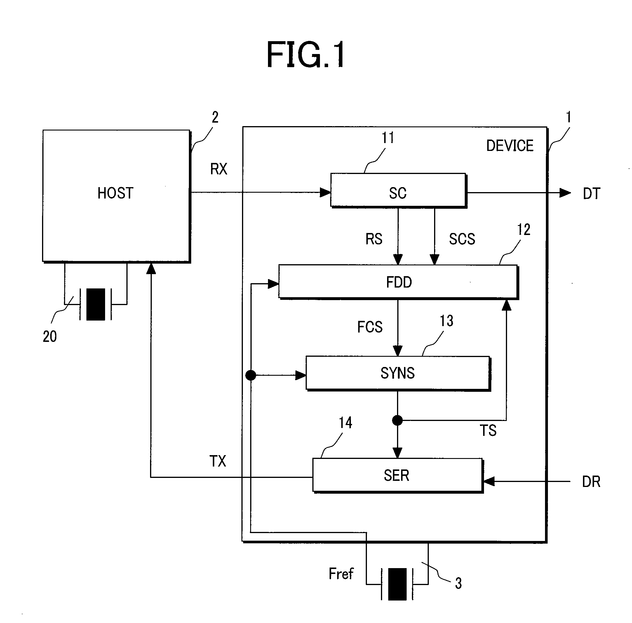
[0076] Embodiment 1 of the present invention will now be explained first with reference to FIGS. 1-12.

[0077]FIG. 1 is a block diagram for explaining an overall configuration of a communication system with an automatic coordination function of transmission signals.

[0078] The communication system according to this embodiment is configured to carry out bidirectional communication a device 1 provided with a transmitting / receiving device having a transmitting / receiving function and a host 2 provided with a transmitting / receiving device having a transmitting / receiving function through automatic coordination of transmission signals from each other. That is, the communication system includes the host 2 which outputs RX to the device 1 and receives TX from the device 1, the device 1 which receives RX from the host 2 and outputs a reception data DT and which receives a transmission data DR and transmits TX to the host 2, and a reference signal generating source 3 inputting a reference signa...

embodiment 2

[0131] A communication system with an automatic coordination function of transmission signals according to a second embodiment of the present invention will now be explained with reference to FIGS. 13-19.

[0132]FIG. 13 is a block diagram for explaining an overall configuration of the communication system according to Embodiment 2.

[0133] The communication system in this embodiment includes a host 2 which outputs RX to a device 1 and receives TX from the device 1, the device 1 which receives RX from the host 2 and outputs a reception data DT and which receives a transmission data DR and transmits TX to the host 2, an oscillator 3 inputting a reference signal Fref to the device 1, and a transmitting / receiving device which includes a case where transmitting / receiving signal frequencies of spread spectrum (SSC) performed by serial ATA and the like are not uniform.

[0134] The device 1 includes a synchronization establishment unit 11 which is inputted the RX the device 1 received, extract...

embodiment 3

[0188] Next, a transmitting / receiving device with an automatic coordination function for transmission according to a third embodiment will be explained with reference to FIG. 22.

[0189] Embodiment 3 is a modification of Embodiment 1. That is, although Embodiment 1 utilized the oscillator 3 as a reference signal generation source, Embodiment 3 utilizes a VCO 15 and a reference voltage generation circuit (BGR) instead of the oscillator to generate a reference signal. By mounting the VCO 15 capable of generating a frequency controlled output signal with a control voltage VB generated by the BGR 16 inside the device 1, it becomes possible to generate a reference signal Fref inside the device 1. This can also be introduced as a modification of Embodiment 2. The transmitting / receiving device (not shown) of the host 2 is configured to operate based on a high-accuracy reference signal generated by a crystal oscillator for example.

[0190] For a configuration of the BGR 16 used in this embodi...


PUM


Abstract

Disclosed is a semiconductor IC device using a low-price oscillator, which is capable of bidirectional communication with a host and features a low price. In bidirectional communication between a host and a device, the device comprises a synchronization establishment unit, a frequency difference detector, a frequency generator, and an oscillator providing a reference signal. The synchronization establishment unit to which an output signal from the host is inputted outputs a received signal, a synchronization establishment signal and a reception data. The frequency difference detector detects a frequency difference between a received signal and a transmitting signal, and outputs a frequency coordination signal to the frequency generator. The number of frequency division of the frequency generator is controlled by the frequency coordination signal, and the frequency generator is capable of matching the frequency of the transmitting signal which is an output signal with the frequency of the received signal.

Description

CROSS-REFERENCE TO RELATED APPLICATIONS [0001] The present application claims priority from Japanese application JP 2005-299863 filed on Oct. 14, 2005, and Japanese application JP 2006-213219 filed on Aug. 4, 2006, the contents of which are hereby incorporated by reference into this application. FIELD OF THE INVENTION [0002] The present invention relates to a transmitting / receiving device and a communication system using the same, and more particularly to a transmitting / receiving device with an automatic coordination function of transmitting signals incorporated in a semiconductor IC device, a recording / reproducing device for example, using a standard I / O device performing a bidirectional between a host and a device or a recording medium inclusive of HDD / CD / DVD / BD (Blue-ray Disc) and so forth, and a communication system using the same. BACKGROUND OF THE INVENTION [0003] In general, a device, e.g., a semiconductor IC device, capable of bidirectional communication with a host uses a s...

Claims


Application Information

Patent Timeline
IPC IPC(8): H04N5/268G06F1/04G06F1/12G06F13/42H04L7/00H04L7/033H04L7/10
CPCG06F1/12H04L7/10H03L7/18H03L7/0995H03L7/183H04B1/40H04W56/00
Inventor KAWAMOTO, TAKASHITAKAHASHI, TOMOAKIKIKUCHI, SHINYAISHIDA, YOSHIMINISHIO, HIROMITSU
Owner RENESAS ELECTRONICS CORP
Learn More