
Optical pickup, optical disc device and method for manufacturing optical pickup

a manufacturing method and optical pickup technology, applied in the manufacture of optical heads, instruments, data recording, etc., can solve the problems of degrading the recording/playback characteristics of optical disks, complicated and enlarged optical pickups, and not applying fine adjustment methods to thin-type optical pickups. , to achieve the effect of simple configuration

Inactive Publication Date: 2007-07-05
SONY CORP
View PDF6 Cites 2 Cited by
  • Summary
  • Abstract
  • Description
  • Claims
  • Application Information

AI Technical Summary

Benefits of technology

The present invention provides an optical pickup with a simple structure that reduces astigmatism without the need for additional means of correcting aberration. The optical pickup includes a collimate lens and an objective lens with mounting angles adjusted to offset astigmatisms, minimizing astigmatism and improving optical performance. The optical disk apparatus and manufacturing method also include adjusting mounting angles to offset astigmatisms, resulting in a more stable and reliable optical pickup.

Problems solved by technology

An optical pickup of an optical disk apparatus has the following problem: a large astigmatism of an objective lens outgoing side spot will degrade record / playback characteristics on an optical disk.
Patent Document 1 Japanese Patent Laid-Open No. 64-76011 However, the above-mentioned method of correcting astigmatism with the anamorphic prism has the following problem: the anamorphic prism causes the optical pickup to be complicated and enlarged.
Accordingly, there is a problem of the fine adjustment method not being applied to a thin type optical pickup.

Method used


Image

  • Optical pickup, optical disc device and method for manufacturing optical pickup
  • Optical pickup, optical disc device and method for manufacturing optical pickup
  • Optical pickup, optical disc device and method for manufacturing optical pickup

Examples


Embodiment Construction

[0023] One embodiment of the present invention will be described in detail with reference to the accompanying drawings.

(1) Overall Configuration of Optical Disk Apparatus

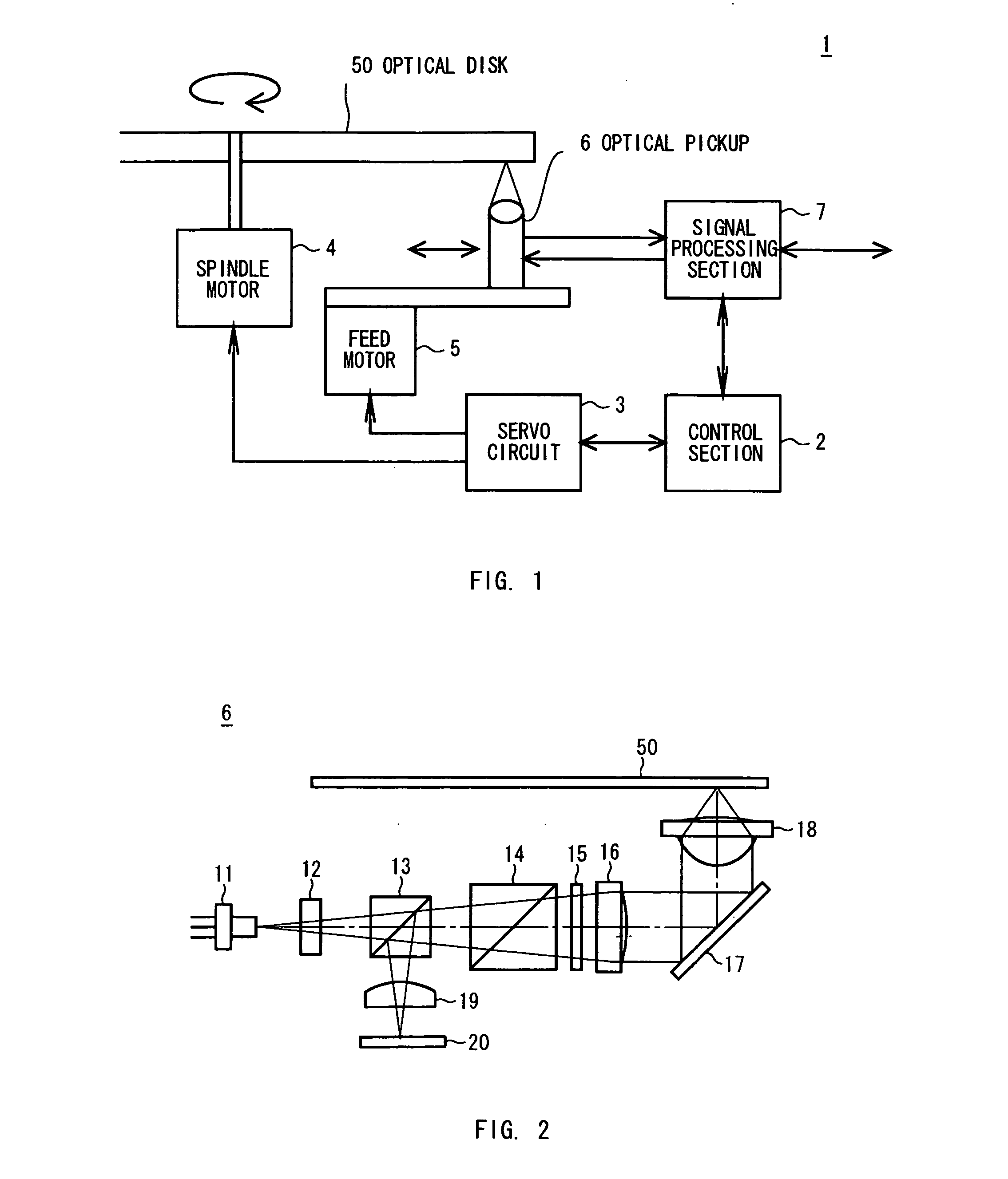
[0024] In FIG. 1, a reference numeral 1 denotes an optical disk apparatus and a control section 2 controls each part of the optical disk apparatus 1.

[0025] That is, the control section 2 rotates a spindle motor 4 through a servo circuit 3 and rotatingly drives an optical disk 50 placed on a turn table (not illustrated). Moreover, the control section 2 rotates a feed motor 5 through the servo circuit 3 and moves an optical pickup 6 in the radial direction of the optical disk 50. Furthermore, the control section 2 controls a signal processing section 7 and executes data read / write from and into the optical disk 50.

[0026] Besides, the control section 2 controls a lens drive of the optical pickup 6 and drives the objective lens of the optical pickup 6 in the tracking direction and the focus direction.

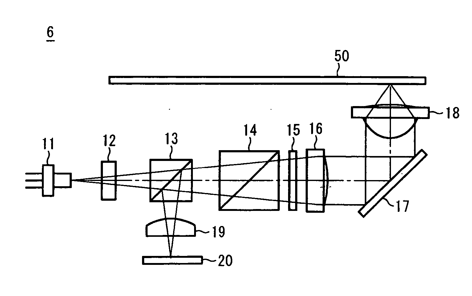
[0027]FIG. 2 ...


PUM

PropertyMeasurementUnit
rotational angleaaaaaaaaaa
angleaaaaaaaaaa

Abstract

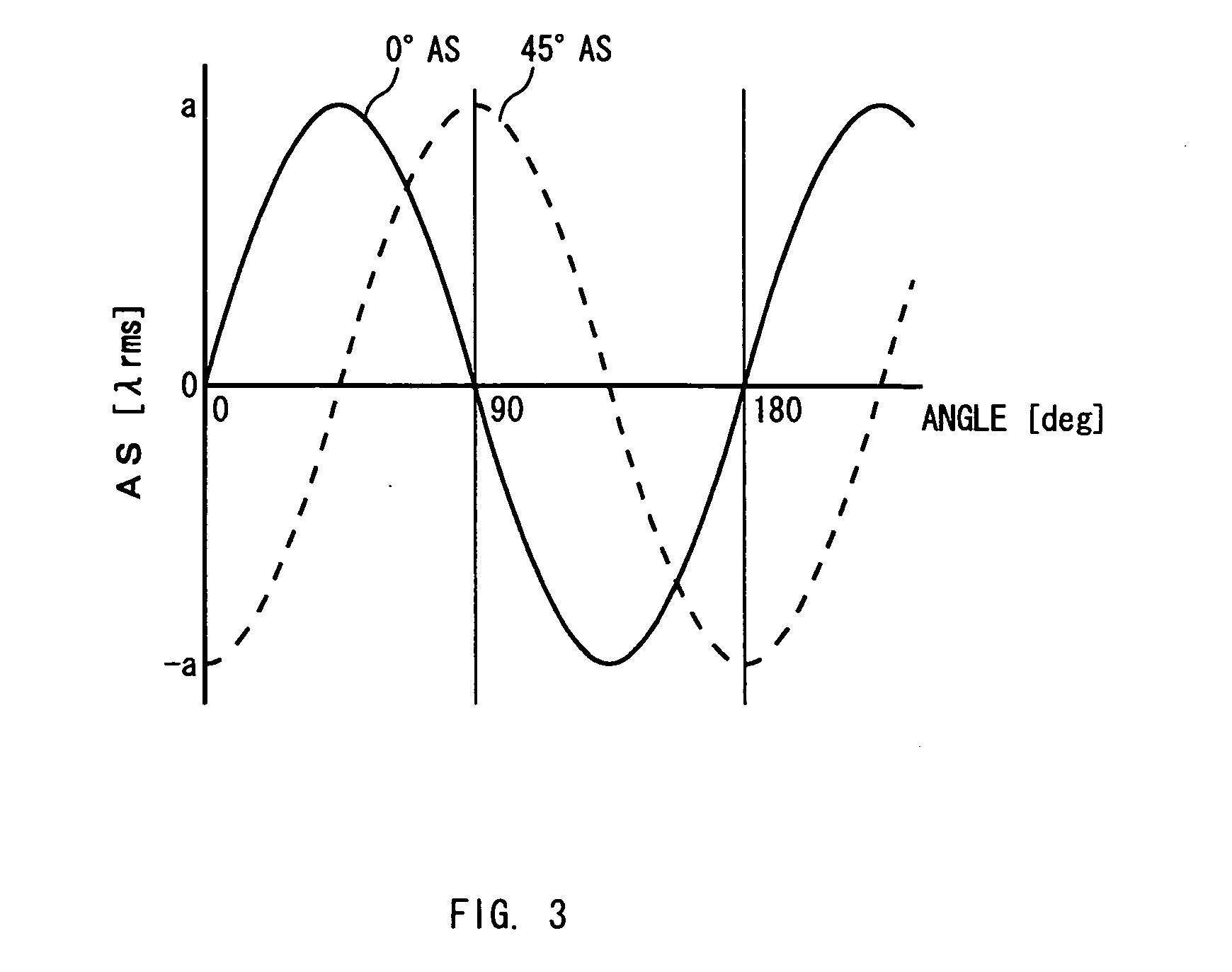
An optical pickup is provided which is capable of minimizing an astigmatism thereof with a simple configuration. The optical pickup 6 includes a collimate lens 16 for transferring optical beams outputted from a laser diode 11 to parallel light, and an objective lens 18 for collecting the optical beams transferred to parallel light with the collimate lens 16 and applying the optical beams to an optical disk 50, wherein mounting angles of the collimate lens 16 and the objective lens 18 are adjusted so that astigmatisms of the collimate lens 16 and the objective lens 18 may be offset by each other. Thus the astigmatism of the optical pickup 6 can be minimized with a simple configuration without need for separately providing means of correcting aberration.

Description

TECHNICAL FIELD [0001] The present invention relates to an optical pickup, an optical disk apparatus and a manufacturing method for the optical pickup, and is optimum to application to an optical disk apparatus by irradiating optical beam to the optical disk for access. BACKGROUND ART [0002] An optical pickup of an optical disk apparatus has the following problem: a large astigmatism of an objective lens outgoing side spot will degrade record / playback characteristics on an optical disk. [0003] As one of correcting such an astigmatism, there is proposed a method of adjusting collimation with an anamorphic prism provided between a collimate lens and an objective lens (for example, refer to Patent Document 1, from the 1st line in the left upper column to the 2nd line in the right upper column at Page 2). [0004] Patent Document 1 Japanese Patent Laid-Open No. 64-76011 However, the above-mentioned method of correcting astigmatism with the anamorphic prism has the following problem: the a...

Claims


Application Information

Patent Timeline
Patent Type & Authority Applications(United States)
IPC IPC(8): G11B7/00G11B7/135
CPCG11B7/1374G11B7/22G11B7/13922G11B7/1376G11B7/08
Inventor KIKUCHI, ATSUOTAKAHASHI, KAZUYUKI
Owner SONY CORP
Learn More