Capacitive microphone and method for making the same

a technology of capacitive microphones and microphones, applied in the field of capacitive microphones, can solve the problems of poor low frequency functionality of the microphone, complex processing of this manufacturing method, and additional fastening structure designs, and achieve the effect of avoiding stiction

Active Publication Date: 2007-07-05
IND TECH RES INST
View PDF5 Cites 47 Cited by
  • Summary
  • Abstract
  • Description
  • Claims
  • Application Information

AI Technical Summary

Benefits of technology

[0010]The diaphragm can be particularly shaped as a round cap. During the drying process of the sacrificial layer after being wet etched, the surface stiction occurs, which is used for fastening the diaphragm. The sacrificial layer at the external periphery is relatively thin, so surface stiction will occur here. The distance between the middle diaphragm and the bottom electrode is relatively high, and there are dimples distributed there-between, thus avoiding the stiction. Annular supporting wall can be further disposed onto the diaphragm. The shape surrounded by the annular supporting wall is the same as that of the air gap. The edge of the air gap can be shaped into an ideal circle by particular design. That is, the edge of the diaphragm is made to be an ideal circle. Of course, another shape, e.g., a square also can be used. The annular supporting wall and the bottom electrode backplate can be fastened via the electrostatic adhesion generated due to the externally-applied bias. In order to prevent the external ring part from drifting during the drying process, the fastening pile can be additionally disposed adjacent to the external ring part, to ensure the relative position of the diaphragm and the bottom electrode.

Problems solved by technology

However, the microphone is a structure with the surrounding parts being fastened during operation, so additional fastening structure designs are required.
The processing of this manufacturing method is relatively complex.
However, the hollow portion of the twist beam spring will result in poor low frequency functionality of the microphone, and the twist beam may be deformed due to the stress gradient of the material.

Method used


Image

  • Capacitive microphone and method for making the same
  • Capacitive microphone and method for making the same
  • Capacitive microphone and method for making the same

Examples


Embodiment Construction

[0028]In order to further understand objects, constructions, features, and functions of the present invention, detailed descriptions are given below with embodiments. It is to be understood that both the foregoing general description and the following detailed description are exemplary, and are intended to provide further explanation of the present invention as claimed.

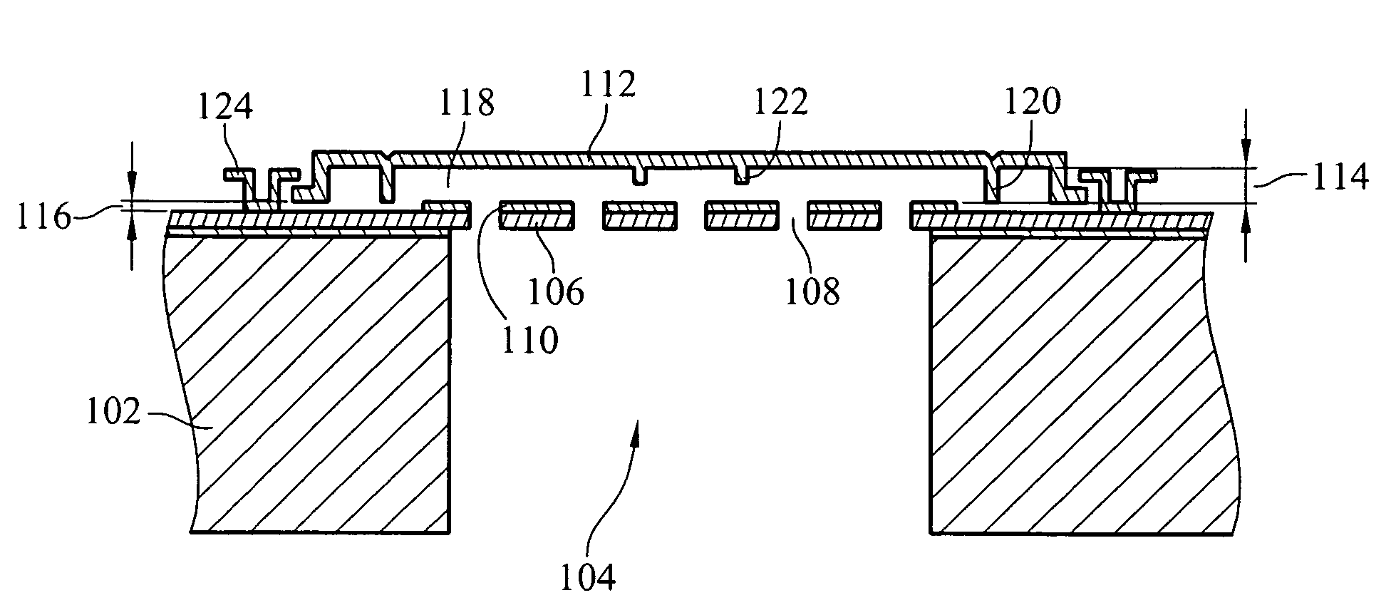
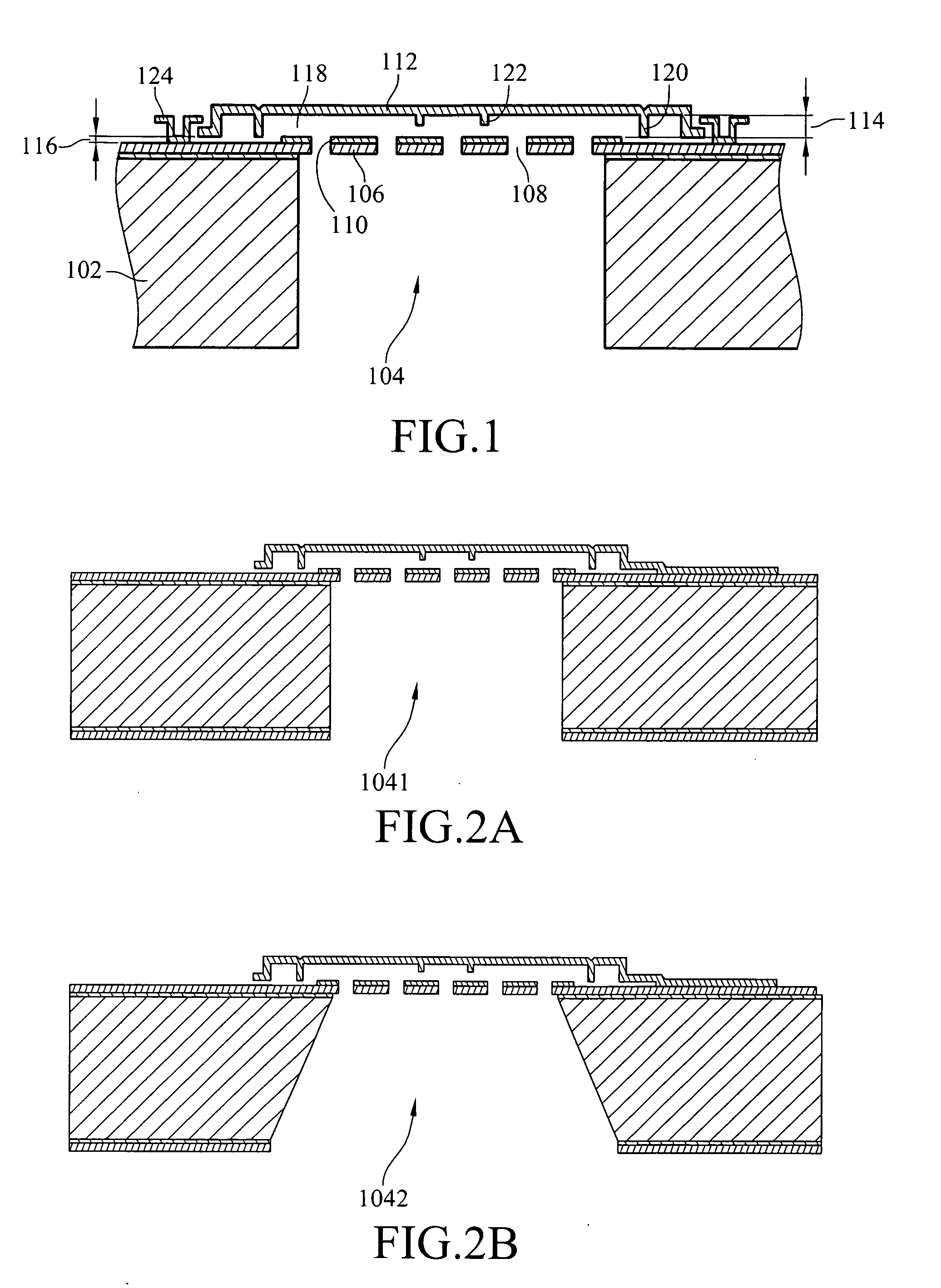
[0029]Referring to FIG. 1, it is a cross-sectional structural view of the capacitive microphone of the present invention. A substrate 102, which can be a silicon wafer and has a cavity 104, is provided. As shown in FIG. 2A, a cavity 1041 shaped into a vertical round hollow can be formed by Inductive Couple Plasma (ICP) dry etching. As shown in FIG. 2B, a cavity 1042 shaped into an inclined surface square hollow is formed by silicon anisotropy wet etching. A backplate 106 is disposed on the substrate 102, and the backplate 106 comprises a plurality of holes 108. An electrode layer 110 made of conductive materials is fu...


PUM

PropertyMeasurementUnit
distanceaaaaaaaaaa
heightaaaaaaaaaa
heightaaaaaaaaaa

Abstract

A capacitive microphone and method for making the same are provided. A backplate with a plurality of holes is formed on a substrate with at least one cavity, and a diaphragm is formed above the backplate. There is an air gap between the backplate and the diaphragm. The air gap and the cavity communicate with each other by each hole. The diaphragm and the backplate are separated by a first distance and a second distance which is smaller than the first distance, such that the difference is formed on the diaphragm. The second distance area is fastened through surface stiction produced by mist or other fluids.

Description

CROSS-REFERENCE TO RELATED APPLICATIONS[0001]This non-provisional application claims priority under 35 U.S.C. §119(a) on Patent Application No(s). 094147532 filed in Taiwan, R.O.C. on Dec. 30, 2005, the entire contents of which are hereby incorporated by reference.BACKGROUND OF THE INVENTION[0002]1. Field of Invention[0003]The present invention relates to a microphone, and more particularly, to a capacitive microphone and method for making the same.[0004]2. Related Art[0005]Most micro capacitive microphones are manufactured through film processes. The remaining stress on the film limits the sensitivity of the microphone to a great extent, which can be released effectively by way of single-end support. However, the microphone is a structure with the surrounding parts being fastened during operation, so additional fastening structure designs are required. As for U.S. Pat. No. 6,535,460, the backplate is located at the top of the structure, and contacts with the polysilicon diaphragm v...

Claims


Application Information

Patent Timeline
Patent Type & Authority Applications(United States)
IPC IPC(8): H04R25/00
CPCH04R19/04Y10T29/435Y10T29/4908Y10T29/49005Y10T29/4902
Inventor CHEN, JEN-YI
Owner IND TECH RES INST
Why Eureka
Try Eureka