Gas turbine engine assembly and methods of assembling same

a technology of gas turbine engines and assembly methods, applied in the direction of machines/engines, bearing unit rigid supports, liquid fuel engines, etc., can solve the problem of relative high differential bearing load

Active Publication Date: 2007-07-12
GENERAL ELECTRIC CO
View PDF21 Cites 39 Cited by
  • Summary
  • Abstract
  • Description
  • Claims
  • Application Information

AI Technical Summary

Benefits of technology

[0004] In one embodiment, a method for assembling a gas turbine engine is provided. The method includes coupling a high-pressure compressor to a high-pressure turbine using ...

Problems solved by technology

As a result, utilizing a known differential bearing in this a...

Method used


Image

  • Gas turbine engine assembly and methods of assembling same
  • Gas turbine engine assembly and methods of assembling same
  • Gas turbine engine assembly and methods of assembling same

Examples


Embodiment Construction

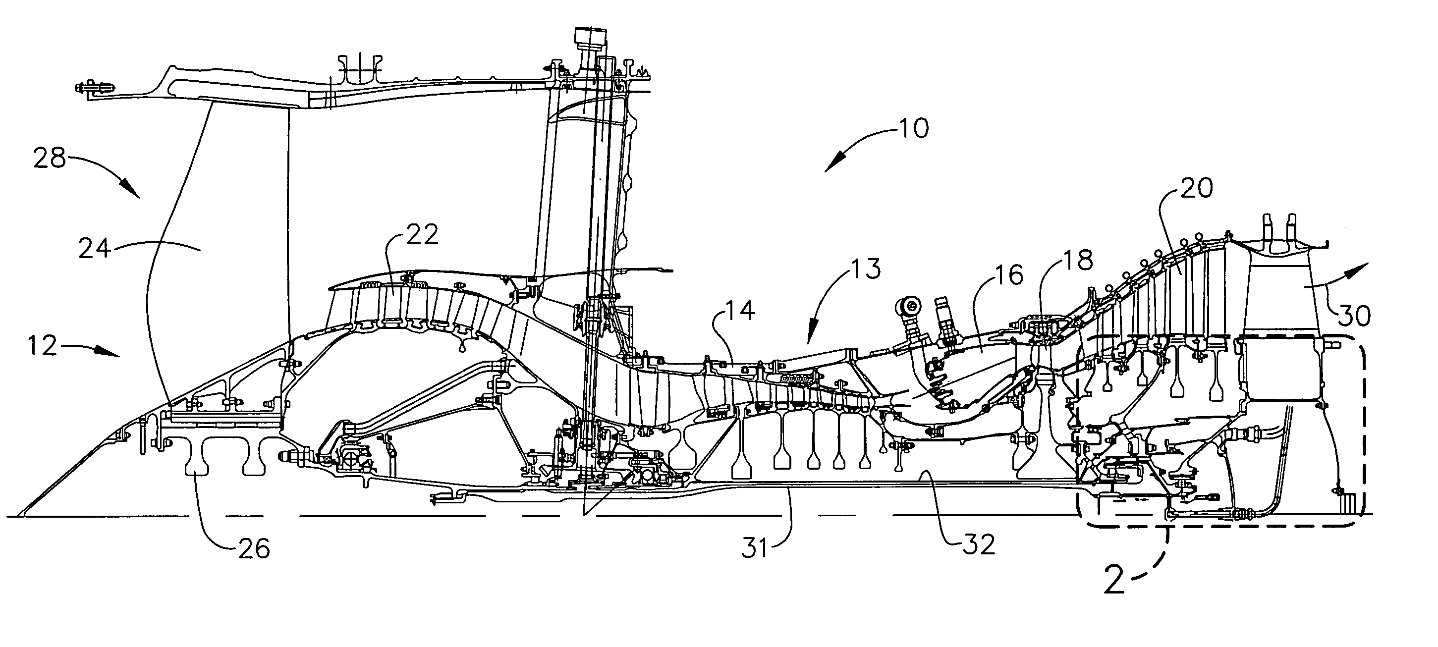
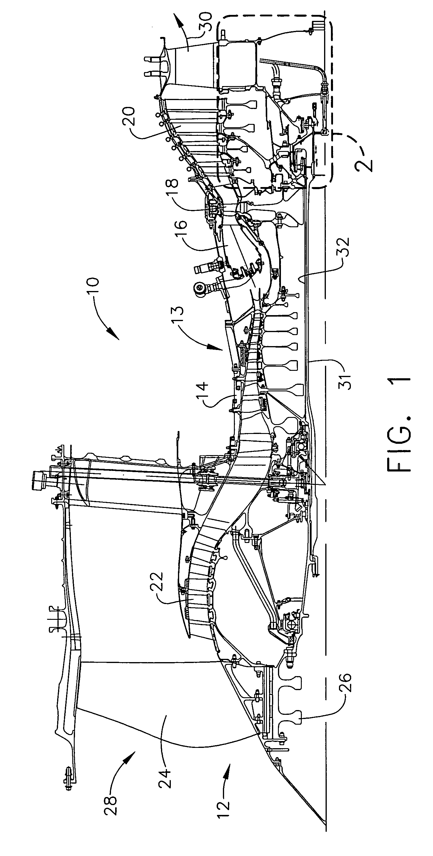
[0010] Referring to the drawings, FIG. 1 is a schematic illustration of a gas turbine engine 10 that includes a fan assembly 12 and a core engine 13 including a high-pressure compressor 14, a combustor 16, and a high-pressure turbine 18. Engine 10 also includes a low-pressure turbine 20, and a booster 22. Fan assembly 12 includes an array of fan blades 24 extending radially outward from a rotor disc 26. Engine 10 has an intake side 28 and an exhaust side 30. Fan assembly 12 and turbine 20 are coupled by a first rotor shaft 31, and compressor 14 and turbine 18 are coupled by a second rotor shaft 32.

[0011] During operation, air flows through fan assembly 12, along a central axis 34, and compressed air is supplied to high-pressure compressor 14. The highly compressed air is delivered to combustor 16. Airflow (not shown in FIG. 1) from combustor 16 drives turbines 18 and 20, and turbine 20 drives fan assembly 12 by way of shaft 31. In one embodiment, shaft 31 rotates in a first directi...


PUM


Abstract

A method for assembling a gas turbine engine includes coupling a high-pressure compressor to a high-pressure turbine using a first shaft, coupling a fan assembly to a low-pressure turbine using a second shaft, and coupling a differential squeeze film damper assembly between the first and second shafts.

Description

BACKGROUND OF THE INVENTION [0001] This invention relates generally to gas turbine engines, and more specifically to gas turbine engine assemblies and methods of assembling the same. [0002] At least some known gas turbine engines include a fan assembly, a core engine, and a power turbine coupled to the fan assembly. The core engine includes at least one compressor, a combustor, a high-pressure turbine coupled together in a serial flow relationship. More specifically, the compressor and high-pressure turbine are coupled through a shaft to define a high-pressure rotor assembly and the low-pressure turbine is coupled to the fan assembly utilizing a second shaft. Air entering the core engine is mixed with fuel and ignited to form a high energy gas stream. The high energy gas stream flows through the high-pressure turbine to rotatably drive the high-pressure turbine such that the shaft, in turn, rotatably drives the compressor. [0003] To maximize the fuel burn in a high-performance turbi...

Claims


Application Information

Patent Timeline
IPC IPC(8): F02K3/072
CPCF01D25/164F02C7/06F16F15/0237F16C27/045F16C2360/23F16C33/6659F05D2240/53F16C19/26F16C33/581F16C33/6677
Inventor MONIZ, THOMAS ORY
Owner GENERAL ELECTRIC CO
Why Eureka
Try Eureka