Thermal to electrical energy converter

a converter and thermal energy technology, applied in the direction of machines/engines, lighting and heating apparatus, magnetic bodies, etc., can solve the problems of increasing the final cost of the electrical energy produced using, and affecting the efficiency of the conversion process, so as to reduce the difference between the pressure inside the hac and the hdc

Inactive Publication Date: 2007-07-12
GREEN GOLD 2007
View PDF10 Cites 11 Cited by
  • Summary
  • Abstract
  • Description
  • Claims
  • Application Information

AI Technical Summary

Benefits of technology

[0083] The converter may comprise a by-pass conduit, the first end of which is connected to the HAC through a valve and the second end of which is connected directly to the HDC. In this case, the method comprises the additional step of opening the valve at the first

Problems solved by technology

For example, transportation of coal and fuel is expensive and raises the final cost of the electrical energy that is produced using them.
In addition, using coal and fossil fuel greatly pollutes the environment.
The conversion efficiency of this technology is known to be very low (usually not more than 10%).
However, these technologies are very expensive, and they produce direct current, which is problematic because many electricity appliances use alternating current.
The efficiency, by wh

Method used


Image

  • Thermal to electrical energy converter
  • Thermal to electrical energy converter
  • Thermal to electrical energy converter

Examples


Embodiment Construction

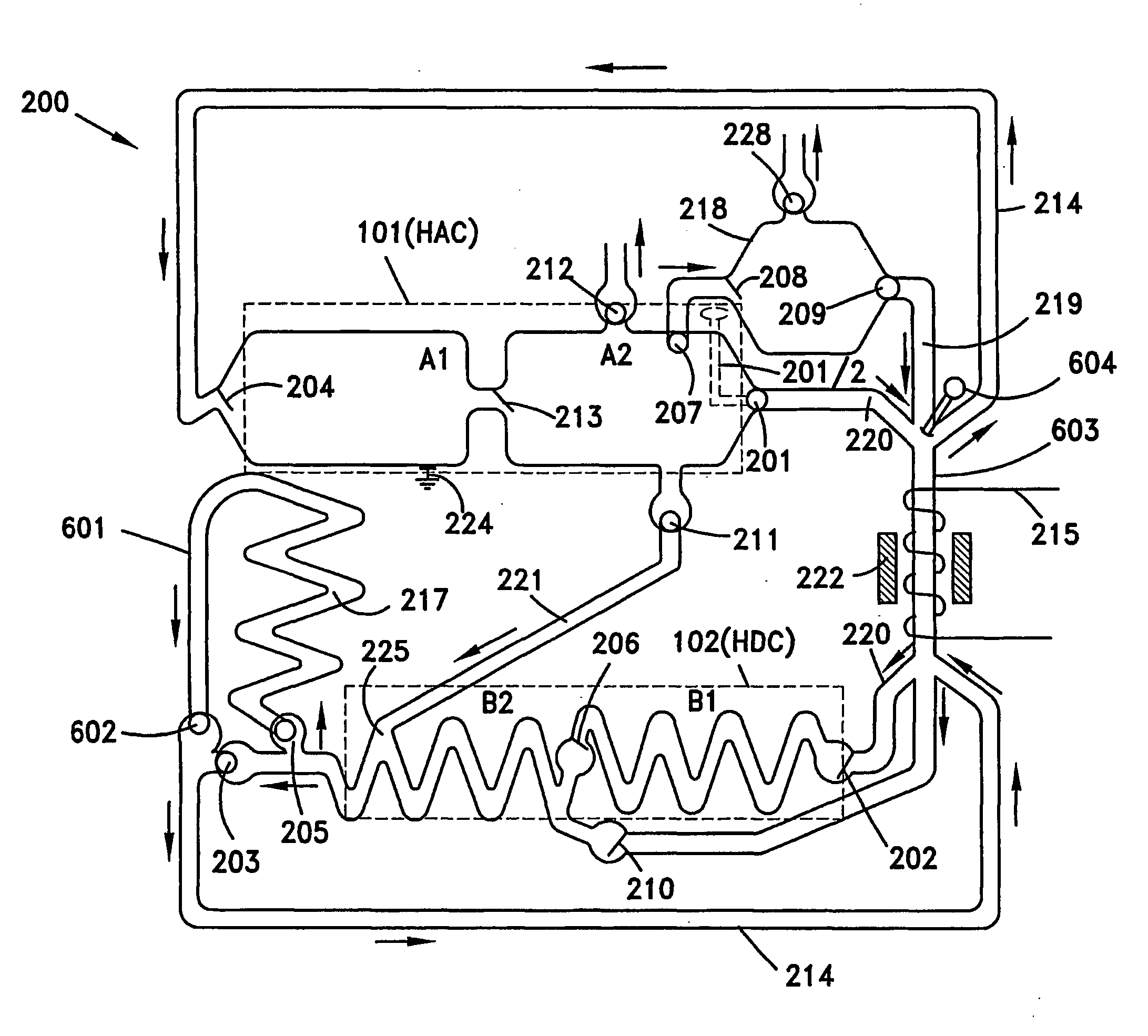
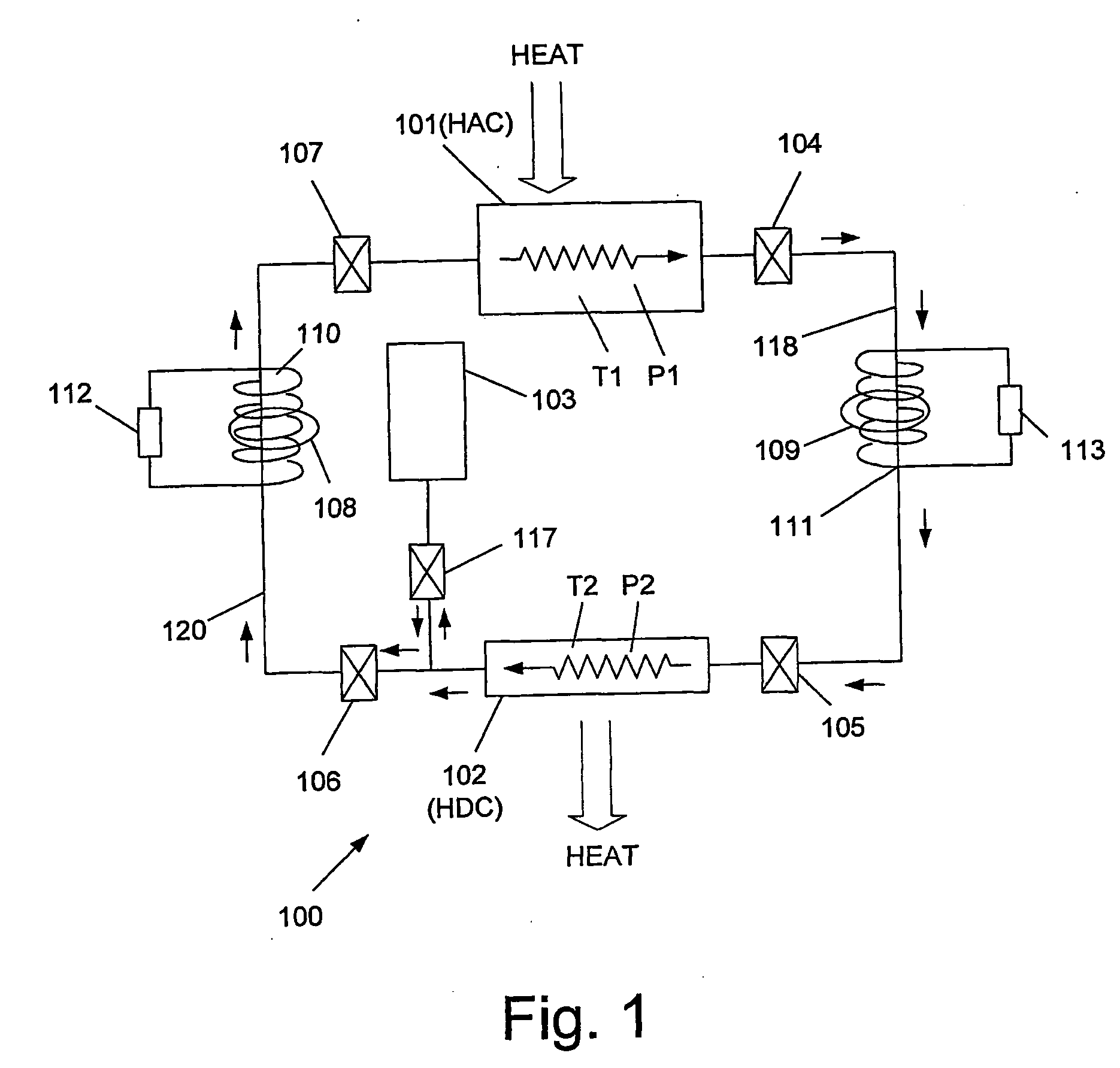
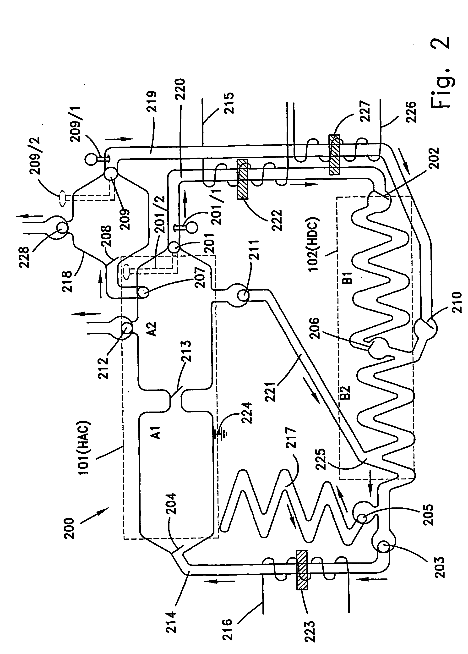
[0093] The energy converter of the invention is basically a device capable of absorbing heat from an external heat source and producing electricity while delivering a portion of the heat to a cold temperature reservoir. The external heat source, which provides the required heat to the converter, can be essentially any heat source. For example, the heat can be provided by a nuclear power station, or from an air condition system, or a compressor or any operating engine or an electric motor. In the preferred embodiment the heat source is the surrounding environment and solar radiation. In contrast to conventional industrial power plants, the present system does not use energy consuming machinery such as compressors or pumps. The working substance of the energy converter of the invention is a ferrofluid with intrinsic magnetic properties instead of superheated steam that is usually utilized in conventional power plants to drive a turbine. The ferrofluid coexists together with its vapor ...


PUM


Abstract

The invention is a converter for converting thermal energy into electrical energy. The energy conversion takes place by causing magnetic particles that are initially suspended in ferrofluid to circulate in the converter and to induce electric currents when they pass through one or more coils of electric wires that are coiled around parts of the conduits of the converter. The particles are caused to circulate around the main circuit of the converter by controlling the local temperature and pressure at different locations in the main circuit. The invention also is a method of using the converter to produce electricity.

Description

FIELD OF THE INVENTION [0001] The present invention relates to the field of energy production. More particularly, the present invention relates to an energy converter unit (hereinafter sometimes simply ‘converter’) for converting thermal energy into electrical energy. BACKGROUND OF THE INVENTION [0002] Currently, the most commonly used electrical energy production technologies still make massive use of fossil fuels, which are used for generating steam. The generated steam imparts rotation of movement to a turbine, the shaft of which is mechanically coupled to a rotor of an electrical generator. Upon rotation of the rotor, electrical energy is produced, the magnitude of which is a function, among other things, of the rotation of speed of the rotor and the size of the generator. Using coal, petroleum or gas for producing electricity has several drawbacks. For example, transportation of coal and fuel is expensive and raises the final cost of the electrical energy that is produced using...

Claims


Application Information

Patent Timeline
IPC IPC(8): F01K13/00F01K
CPCF24J2/07H02K44/08H01F1/447F28D15/00F24S20/20
Inventor MORGENSTEIN, HAIM
Owner GREEN GOLD 2007
Why Eureka
Try Eureka