Respirator with active dehumidification

a technology of respirator and active dehumidification, which is applied in the field of respirator, can solve the problems of inability to avoid condensation formation, limited quantity of moisture can be stored, and inability to prevent condensation formation

Inactive Publication Date: 2007-07-12
DRAGERWERK AG
View PDF7 Cites 37 Cited by
  • Summary
  • Abstract
  • Description
  • Claims
  • Application Information

AI Technical Summary

Benefits of technology

[0005] The basic object of the present invention is to provide a respirator in which the moisture in the breathing gas is

Problems solved by technology

The problem in breathing gas humidification is to adjust the humidity supplied to the velocity of flow and to the gas flow.
However, it cannot be avoided that the formation of water of condensation will nevertheless take place within the respiration system.
The problem is additionally aggravated in the c

Method used


Image

  • Respirator with active dehumidification
  • Respirator with active dehumidification
  • Respirator with active dehumidification

Examples


Embodiment Construction

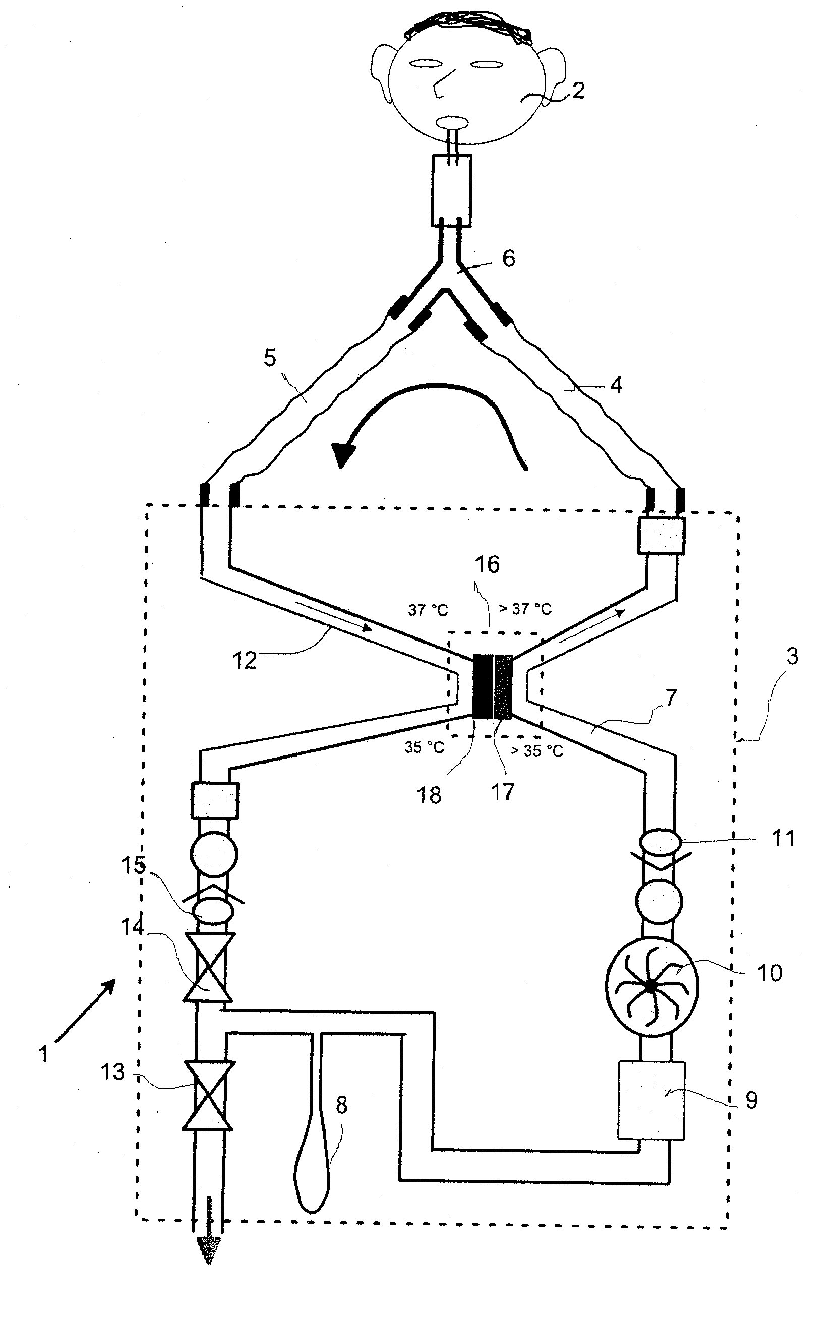
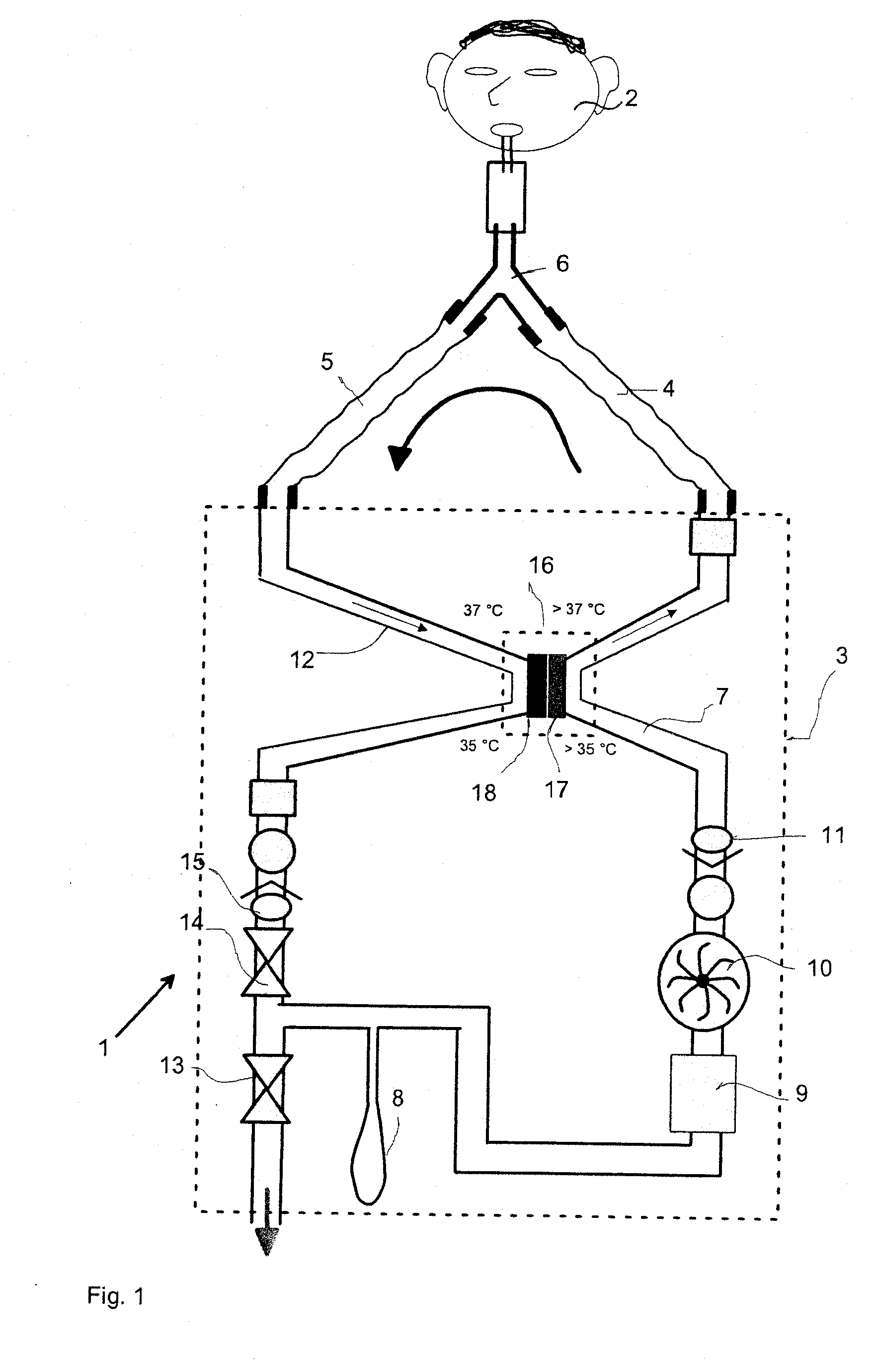
[0021] Referring to the drawings in particular, FIG. 1 schematically illustrates a respirator 1 for a patient 2, in which a breathing system 3 with breathing air circulation via a flexible inspiration tube 4, a flexible expiration tube 5 and a Y-piece 6 is connected to the patient 2.

[0022] A breathing bellows 8, a carbon dioxide absorber 9, a fan 10, an inspiration valve 11 and an expiration line 12 connected to the inspiration line 7, an excess gas outlet valve 13, a peep valve 14 and an expiration valve 15 are located in an inspiration line 7 of the respiration system 3. The inspiration line 7 and the expiration line 12 are thermally coupled with one another via a Peltier element 16. The warm side 17 of the Peltier element 16 is arranged in the inspiration line 7 and the cold side 18 in the expiration line 12. The breathing gas in the inspiration line 7, which gas is being delivered by the fan 10 with a temperature of about 35° C., is heated by the Peltier element 16 to a value s...


PUM


Abstract

A respirator with active dehumidification of the breathing gas has a breathing gas cooler in the form of a Peltier element (16), whose warm side is arranged in the inspiration branch (4, 7) and whose cold side (18) is arranged in the expiration branch (5, 12).

Description

CROSS REFERENCE TO RELATED APPLICATIONS [0001] This application claims the benefit of priority under 35 U.S.C. § 119 of German Patent Application DE 10 2005 062 18 5.6 filed Dec. 23, 2005, the entire contents of which are incorporated herein by reference.FIELD OF THE INVENTION [0002] The present invention pertains to a respirator (also known as a ventilator) with an inspiration branch and an expiration branch. BACKGROUND OF THE INVENTION [0003] There are various different possibilities of heating and humidifying breathing air. The goal is to supply the patient with humid and preheated air. The problem in breathing gas humidification is to adjust the humidity supplied to the velocity of flow and to the gas flow. This adjustment is necessary to avoid overheating of the breathing gas, on the one hand, and to extensively prevent the formation of water of condensation, on the other hand. Breathing gas humidifiers in which water is heated in a water reservoir and is fed into the flowing b...

Claims


Application Information

Patent Timeline
IPC IPC(8): A62B7/00A61M16/00
CPCA61M2205/3673A61M16/16A61M2205/3368A61M16/1075A61M16/1095A61M16/0066A61M16/0808A61M16/01A61M16/0069A61M16/22
Inventor RADOMSKI, KLAUSGERDER, HENNING
Owner DRAGERWERK AG
Why Eureka
Try Eureka