Flexible floating ring seal arrangement for rotodynamic pumps

a rotodynamic pump and flexible technology, applied in the field of rotodynamic pumps, can solve the problems of increased wear, increased wear, and subsequent loss of pump performance, and achieve the effect of restricting fluid recirculation and wear

Inactive Publication Date: 2007-07-12
WEIR SLURRY GRP INC
View PDF16 Cites 18 Cited by
  • Summary
  • Abstract
  • Description
  • Claims
  • Application Information

AI Technical Summary

Benefits of technology

[0018] The particular placement of the flexible floating ring arrangement in a radially-extending axial gap between the rotating and non-rotating elements of the pump provides a more effective restriction of fluid recirculation and wear than is effected with sealing arrangements that are positioned in an axially-extending radial gap between rotating and non-rotating pump elements.

Problems solved by technology

Such fluid recirculation, typically characterized as leakage, results in a consequent loss of pump performance and, in the presence of solid particles, a dramatic increase in wear.
When pumps are used to process slurries, the abrasive particulate matter in the slurry causes wearing between rotating and non-rotating (i.e., stationary) elements of the pump.
The wear dramatically increases when fluid recirculation occurs as previously described.
It has to be noted that in general, axially-extending radial gaps are not well-suited for handling slurries due to high probability of solid particle entrapment between the rotating and non-rotating elements causing rapid wear in the pump elements.
As a result, such seal arrangements may still be vulnerable to undesirable fluid recirculation and wear between rotating and stationary elements of the pump.
Moreover, placement of a sealing arrangement near the eye of the impeller in an axially-extending gap between the casing and impeller does not present the most effective means of preventing solid particle entrapment and subsequent wear between the casing and impeller.

Method used


Image

  • Flexible floating ring seal arrangement for rotodynamic pumps
  • Flexible floating ring seal arrangement for rotodynamic pumps
  • Flexible floating ring seal arrangement for rotodynamic pumps

Examples


Embodiment Construction

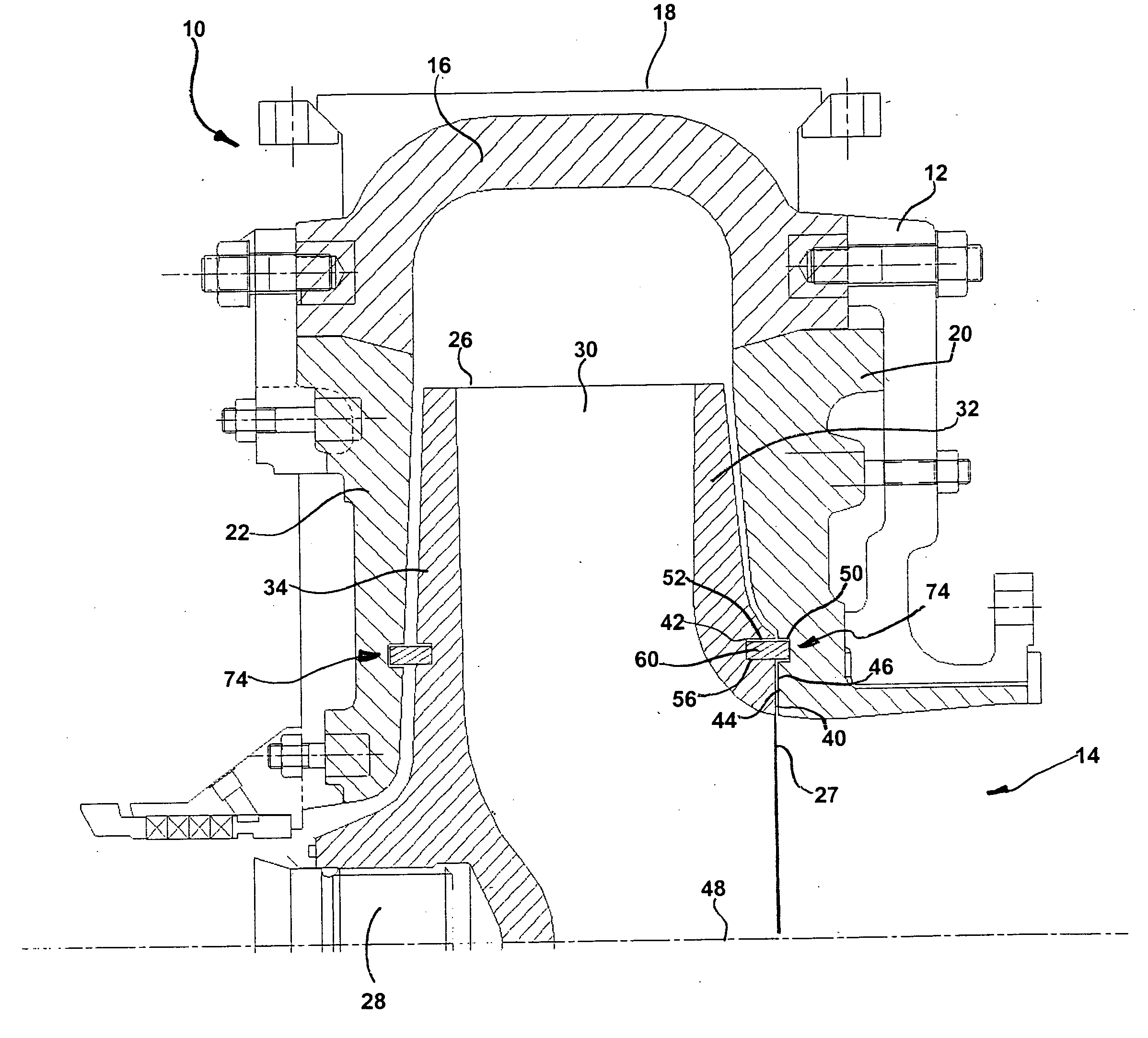
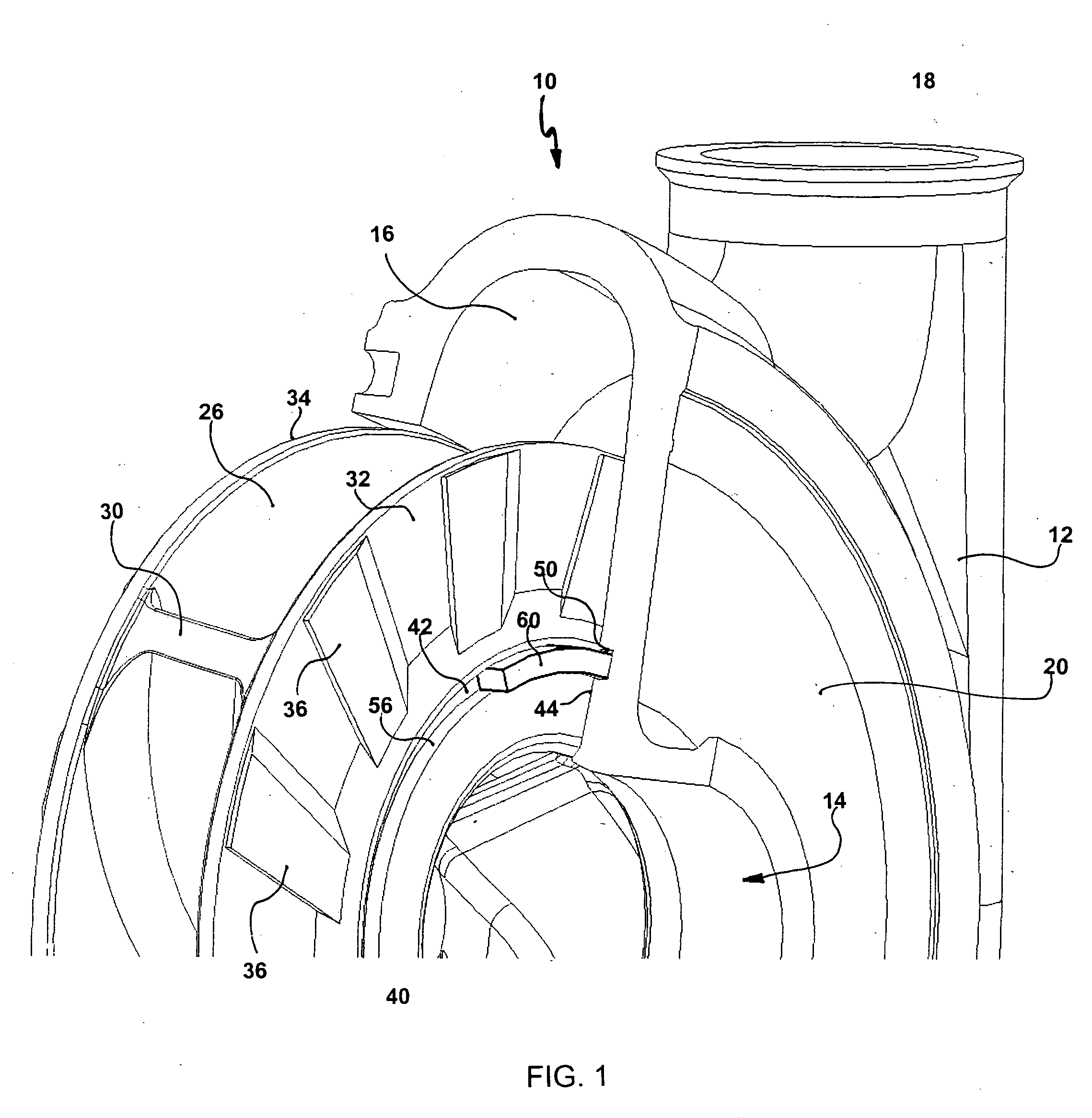
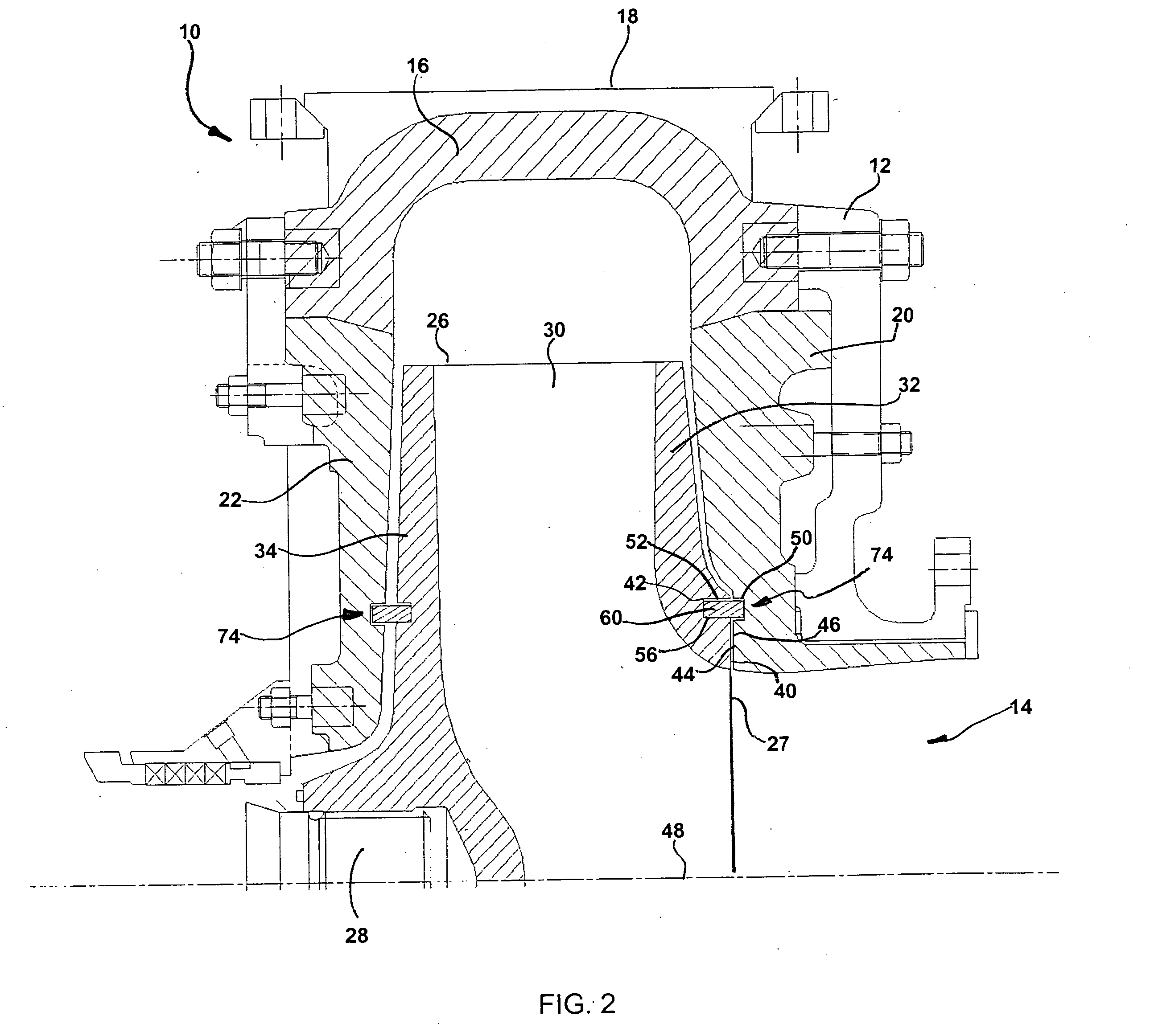
[0027]FIGS. 1 and 2 illustrate a portion of a rotodynamic pump 10 generally comprising a pump casing 12. The illustrated pump casing 12 is generally structured with an axially positioned fluid inlet 14, a volute section 16 and a tangentially-extending fluid outlet or discharge 18. In the particular pump casing 12 configuration that is illustrated in FIG. 1, the pump casing 12 is further structured with an integral suction side liner 20 and an integral drive side liner 22 (not viewable in FIG. 1). Alternatively, the pump casing 12 may be formed with a separate suction side liner 20 and separate drive side liner 22 as shown in FIG. 2.

[0028] The illustrated pump is of a centrifugal slurry type. However, the configuration of the rotodynamic pump 10 illustrated in FIGS. 1 and 2 is by way of example only and the floating ring seal arrangement of the present invention is not limited to use in the type of pump illustrated.

[0029] The pump 10 is further comprised of an impeller 26 that rota...


PUM


Abstract

A floating ring seal arrangement for rotodynamic pumps comprises a flexible ring that is structured to fit within a circular channel formed by generally concentric grooves in the rotating and non-rotating elements of the pump, the ring further being sized to rest against the inner diameter of the groove of the rotating element when static, and capable of radially expansion under centrifugal forces to cause the flexible ring to float in the circular channel during operation of the pump, or deformation under centrifugal or pressure forces such that gaps between the flexible ring and groove in the non-rotating element are minimized or eliminated.

Description

BACKGROUND OF THE INVENTION [0001] 1. Field of the Invention: [0002] This invention relates to rotodynamic pumps, and specifically relates to means for restricting fluid recirculation and for reducing wear between rotating and non-rotating elements of rotodynamic pumps, particularly those pumps suitable for handling slurries. [0003] 2. Description of Related Art: [0004] Rotodynamic pumps, such as centrifugal pumps, are commonly known and used for pumping fluids in many types of industries and for many applications. Such pumps generally comprise an impeller (rotating element) housed within a pump casing (non-rotating element) having a fluid inlet and fluid outlet, or discharge. The impeller is typically driven by a motor external to the casing. The impeller is positioned within the casing so that fluid entering the inlet of the casing is delivered to the center, or eye, of the impeller. Rotation of the impeller acts on the fluid primarily by the action of the impeller vanes which, co...

Claims


Application Information

Patent Timeline
Patent Type & Authority Applications(United States)
IPC IPC(8): F04D29/08
CPCF04D7/04F04D29/167
Inventor ROUDNEV, ALEKSANDERKOSMICKI, RANDY
Owner WEIR SLURRY GRP INC
Why Eureka
Try Eureka