Hemostatic agent delivery system

a technology of hemostatic agent and delivery system, which is applied in the direction of drug composition, bandages, extracellular fluid disorder, etc., can solve the problems of generating a considerable amount of heat, bleeding or acute hemorrhaging is a leading cause of death in trauma cases among civilians, and not quickly or properly addressed, so as to facilitate clotting, facilitate clotting, and facilitate clotting

Active Publication Date: 2007-07-12
MENTKOW JACK +1
View PDF30 Cites 55 Cited by
  • Summary
  • Abstract
  • Description
  • Claims
  • Application Information

AI Technical Summary

Benefits of technology

[0015] The present invention is directed to a hemostatic agent delivery system which is structured to deliver a hemostatic agent directly to a hemorrhage site, for example, a lacerated artery, so as to facilitate clotting of the blood and terminat...

Problems solved by technology

It has long been known that injuries which result in excessive bleeding if not quickly or properly addressed can often prove fatal.
Unfortunately, this fact is well supported by data gathered during numerous armed conflicts throughout time.
As above, with respect to injuries sustained during battle, bleeding or acute hemorrhaging is a leading cause of death in trauma cases among the civilian population.
However, it has been observed that the absorption process affected by this zeolite is a highly exothermic reaction which generates a considerable amount of heat.
More specifically, temperatures ranging from 90° to 100° C. have been reported following use of the material, causing second degree burns to soldiers injured and treated with this product in Iraq, as well as to those persons administering the product, even though personnel administering this product must be trained and certified to administer the same.
A further drawback to this product is that the zeolite material is packaged to be simply poured on to an open wound, however, in the case of hemorrhaging of any significance, such as may occur due to laceration of a major artery, the pressure of blood exiting the wound will simply cause the material to be dispersed thereby minimizing and/or eliminating the effectiveness of the clotting p...

Method used


Image

  • Hemostatic agent delivery system
  • Hemostatic agent delivery system
  • Hemostatic agent delivery system

Examples


Embodiment Construction

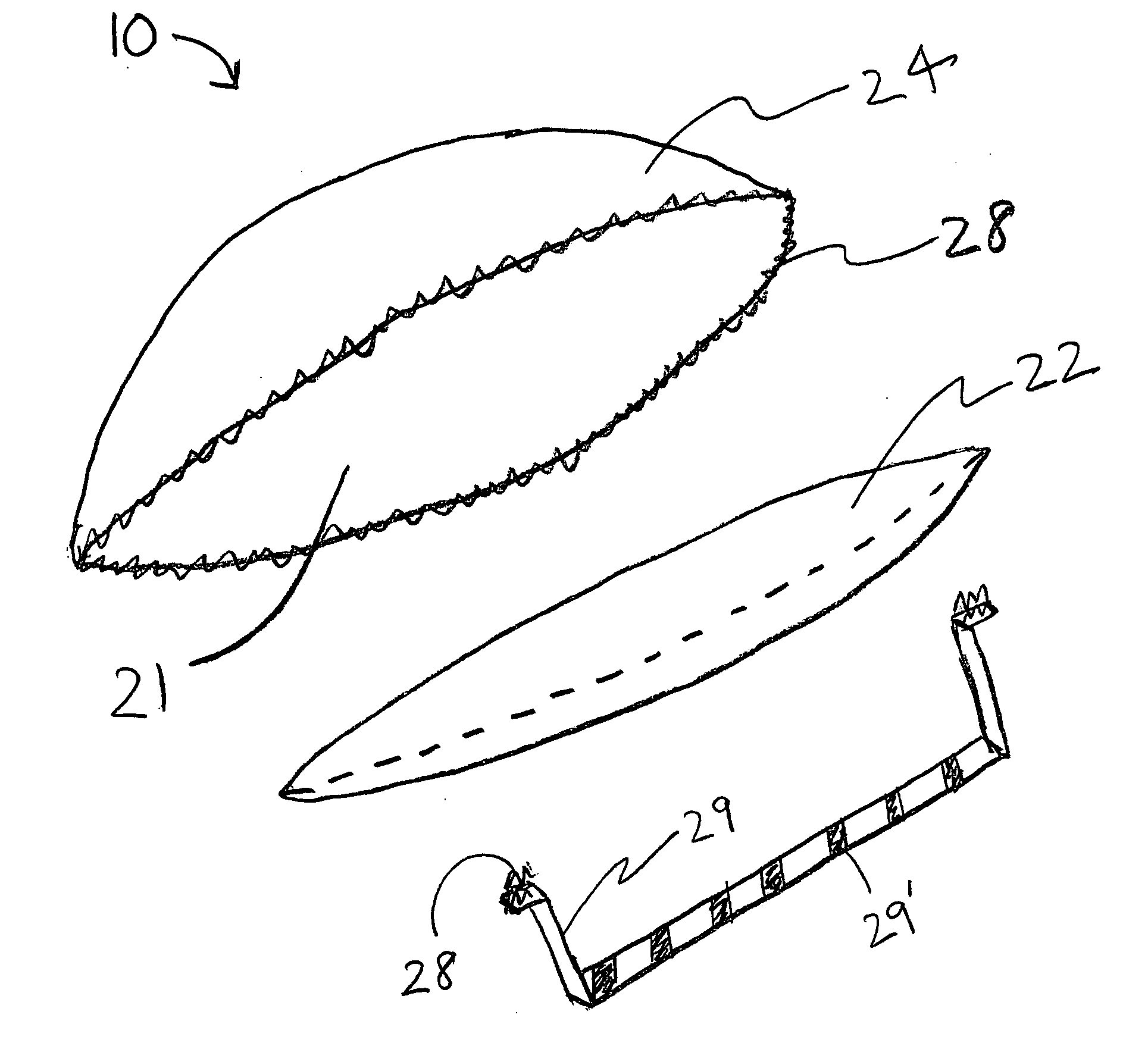
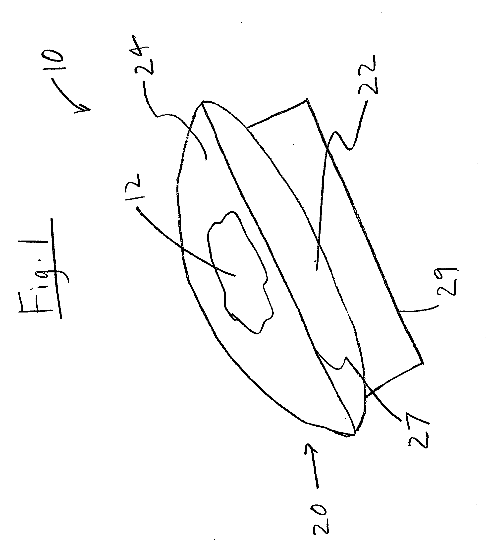
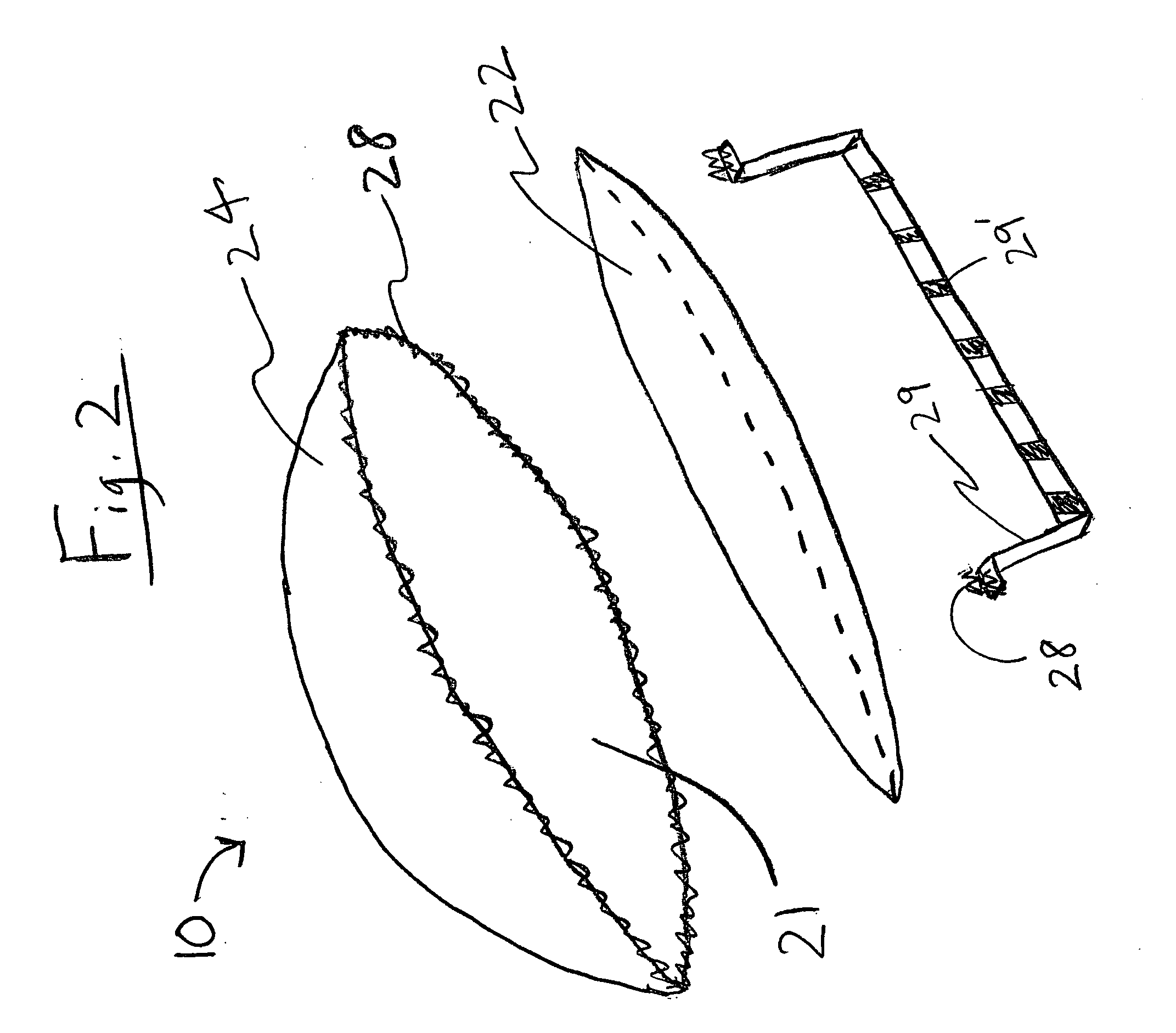
[0027] As previously noted, the present invention is directed to a hemostatic agent delivery system, generally as shown as 10 in the figures, which is structured to facilitate delivery of a hemostatic agent directly proximate a hemorrhage site. More in particular, the present invention is directed towards a hemostatic agent delivery system 10 which may be quickly and effectively utilized to facilitate clotting and to control and / or terminate hemorrhaging of an injured person, such as, a soldier wounded on a battle field, by personnel with minimal training. As will become apparent from the following, the hemostatic agent delivery system 10 of the present invention is structured such that personnel with minimal instruction in its use will be able to readily identify the proper orientation of the delivery assembly 20, so as to facilitate disposition of the delivery assembly 20 directly proximate a hemorrhage site.

[0028] To reduce and / or terminate excessive bleeding at a hemorrhage sit...


PUM

PropertyMeasurementUnit
Coloraaaaaaaaaa
Solubility (mass)aaaaaaaaaa
Sterileaaaaaaaaaa

Abstract

A hemostatic agent delivery system includes a hemostatic agent which is inert and non-reactive yet is capable of forming a stable clot when applied to an actively bleeding wound. The system also includes a delivery assembly to structure to facilitate delivery of the hemostatic agent proximate the hemorrhage site. More specifically, the delivery assembly is structured to releasably contain the hemostatic agent via a release member which is disposed in cooperative relation with a support member which contains the amount of the hemostatic agent. The release member is structured of a soluble material such that it will at least partially dissolve and release the hemostatic agent upon disposition proximate the hemorrhage site. The delivery assembly further comprises a handle member structured to facilitate delivery of the hemostatic agent to the hemorrhage site.

Description

CLAIM OF PRIORITY [0001] The present application is based on and a claim to priority is made under 35 U.S.C. Section 119(e) to provisional patent application currently pending in the U.S. Patent and Trademark Office having Ser. No. 60 / 757,459 and a filing date of Jan. 9, 2006.BACKGROUND OF THE INVENTION [0002] 1. Field of the Invention [0003] The present invention is directed to a hemostatic agent delivery system comprising a delivery assembly having a pouch or receptacle containing a hemostatic agent, the pouch being at least partially defined by a support number in combination with an overlying release member made of a soluble material. More in particular, the hemostatic agent delivery system is structured such that a hemostatic agent is delivered directly to a source of bleeding, and wherein the hemostatic agent is concentrated and retained at the bleeding source to facilitate clotting and terminate hemorrhaging. [0004] 2. Description of the Related Art [0005] It has long been kn...

Claims


Application Information

Patent Timeline
IPC IPC(8): A61F13/00
CPCA61F13/00034A61F13/00059A61F13/00063A61F2013/00153A61F2013/00472A61F2013/00536A61F2013/0054A61F2013/00642A61F2013/00982A61L15/18A61L15/24A61L15/28A61L15/44A61L2300/418A61L2300/602A61L2400/04A61P7/04C08L31/04C08L1/28
Inventor MENTKOW, JACKMENTKOW, LISA
Owner MENTKOW JACK
Why Eureka
Try Eureka