

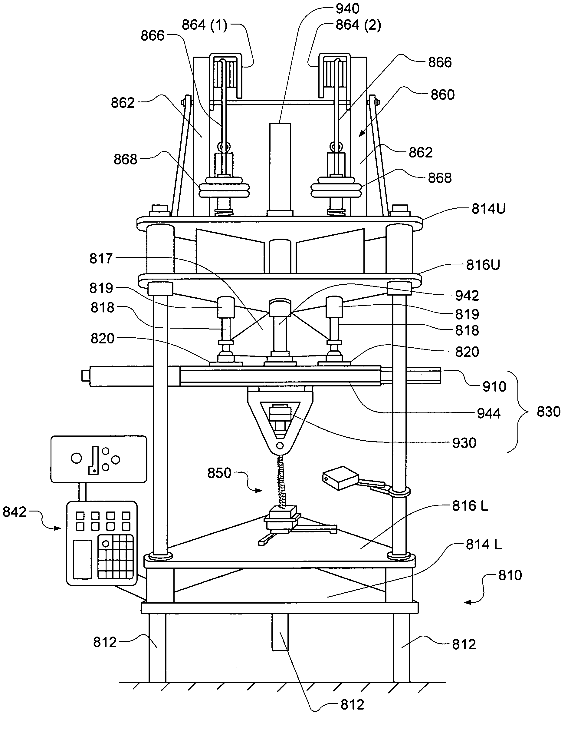
Multi-axis, programmable spine testing system
a testing system and multi-axis technology, applied in the field of coupled joint testing systems, can solve the problems of state-of-the-art testing devices that cannot reproduce a full range of human movements, state-of-the-art testing devices may not accurately apply loads in a multi-axial environment, and cannot replica
- Summary
- Abstract
- Description
- Claims
- Application Information
AI Technical Summary
Benefits of technology
Problems solved by technology
Method used
Image

Examples
Embodiment Construction
Definitions
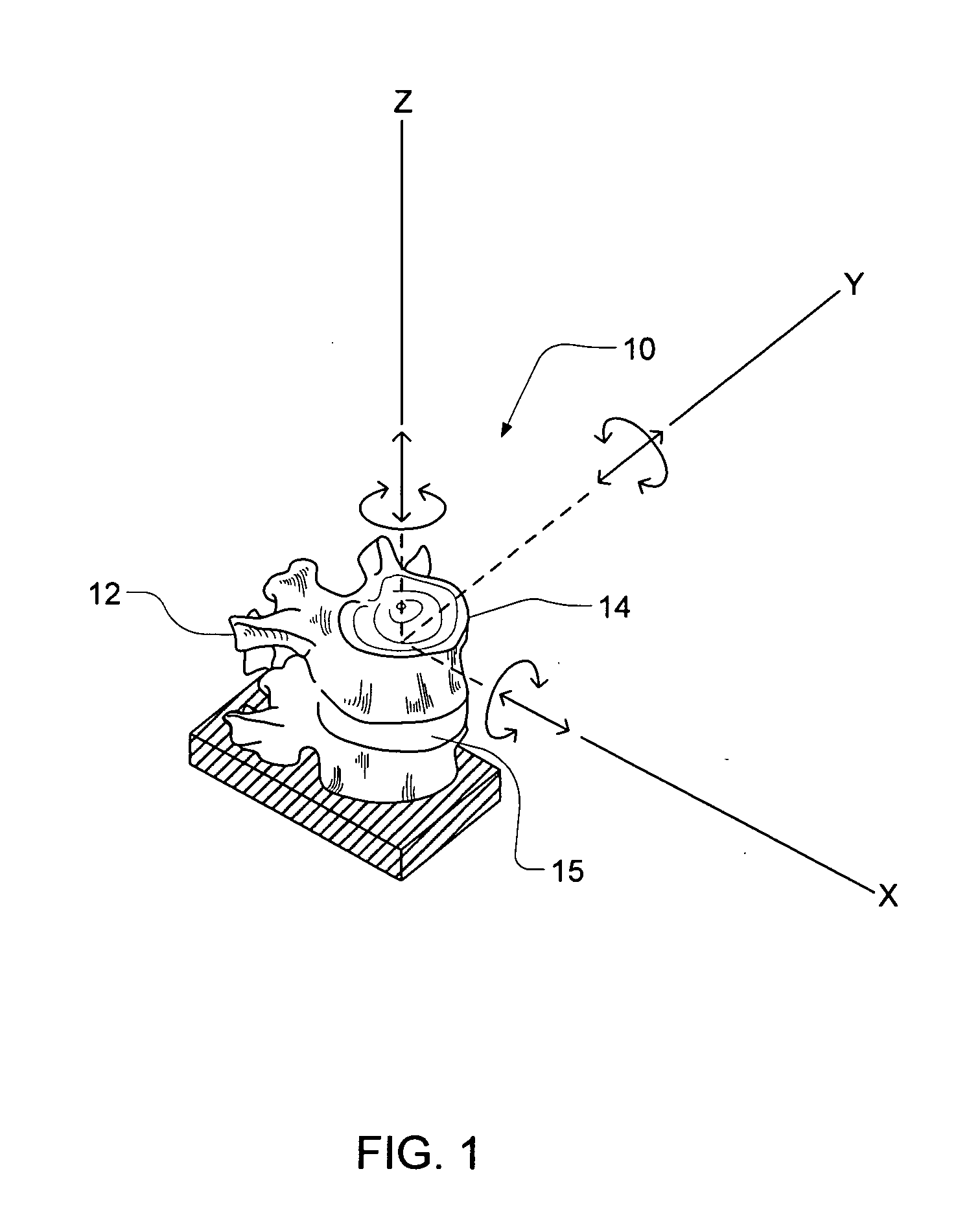
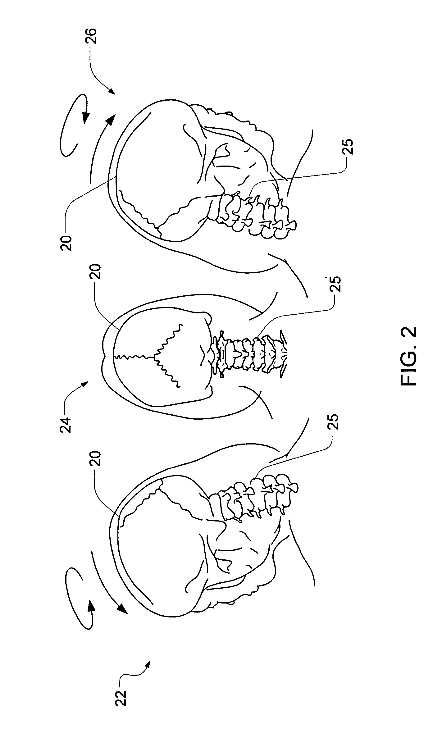
[0055] The term “coupled joint” refers to joints within the human body that enjoy relative motion. Nonlimiting examples of a coupled joint include various spinal vertebrae such as the cervical, thoracic and lumbar vertebrae.
[0056] The term “spinal implant” refers to any natural or artificial device or instrumentation of any composition that may be either permanently or temporarily installed into the human spine. A non-limiting example is a disc replacement device. Instrumentation may include fusion devices, restoration devices, and motion preservation devices.
[0057]“Controller” means any system that provides input in order to control motion and force parameters. Non-limiting examples include vision-guided and encoder position-guided systems.
[0058] The term “force” means load, and includes both torque and force.
[0059] The term “actuation system” means any system designed to provide mechanical input such as motion or force.
[0060] The term “control system” means any sy...
PUM
 Abstract
Description
Claims
Application Information