
Method and System for Dynamic Network Intrusion Monitoring, Detection and Response

a dynamic network and intrusion detection technology, applied in the field of network security, can solve problems such as system administrators who do not have the time or ability to read through large amounts of constantly updated audit information, and cannot be continuously monitored by hackers

Inactive Publication Date: 2007-07-12
BT AMERICAS
View PDF22 Cites 115 Cited by
  • Summary
  • Abstract
  • Description
  • Claims
  • Application Information

AI Technical Summary

Benefits of technology

"The patent text describes a system for managing and prioritizing requests and diagnostics from customers. The system uses various fields to describe the nature of the request or diagnosis, and includes a memo diary to keep track of relevant notes and attachments. The system also allows for the creation of a summary of the diagnosis and its impact on the customer. The technical effect of this system is to improve the efficiency and accuracy of managing customer requests and diagnostics, and to provide a better service to customers."

Problems solved by technology

But because such products cannot be relied upon to work perfectly, and because security bugs may exist in other software or hardware, complete network security also requires monitoring, detection and response in the event of a breach.
System administrators normally do not have the time or ability to read through large amounts of constantly updated audit information, looking for attacks on their systems.
They also do not have the time to continuously monitor hacker activities, looking out for new tactics, tools and trends.
Finally, they do not have the time to become experts on every kind of intrusion and to maintain that expertise.

Method used


Image

  • Method and System for Dynamic Network Intrusion Monitoring, Detection and Response
  • Method and System for Dynamic Network Intrusion Monitoring, Detection and Response
  • Method and System for Dynamic Network Intrusion Monitoring, Detection and Response

Examples


example message

“001f 00003333 1111 2222X ALRT 12345678”

Notes [0125] 1. All the above fields should have spaces between them. [0126] 2. The first four-digit group is the length of everything after it (LENGTH) (the space through the end of “12345678”). [0127] 3. The second four-digit group is the revision field (REVISION). [0128] 4. The third four-digit group is the probe / sentry number, which identifies a particular probe / sentry (“3333” in the example). [0129] 5. The fourth four-digit group is the reference number defined by the probe / sentry system (REFNUM)(“1111” in the example). [0130] 6. The fifth four-digit group is the status number defined by the probe / sentry system (STATUS) (“2222” in the example). [0131] 7. The next one-digit field (“X”) is the keyed Media Access Control (KMAC) value, if present. If not present, the value should be an “X.”[0132] 8. The next field is the op code (OPCODE). For filter-related messages, it is always “ALRT.”[0133] 9. The portion of the message after the space af...


PUM


Abstract

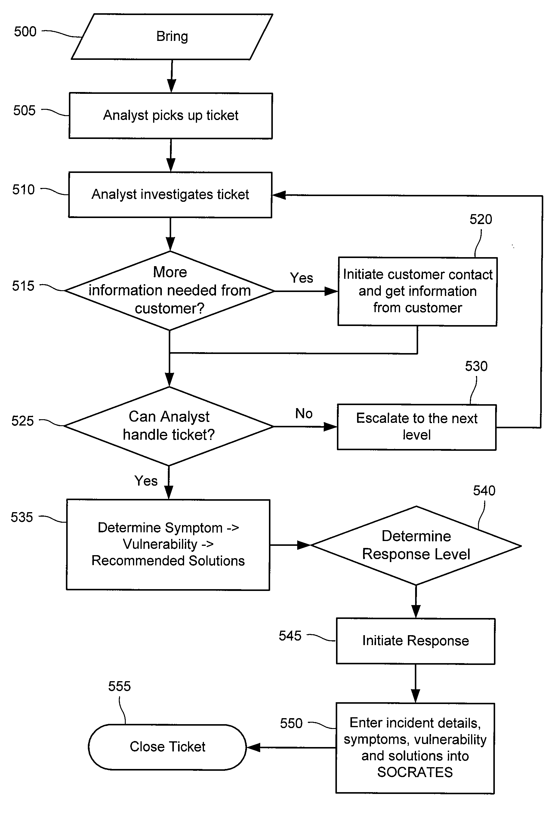
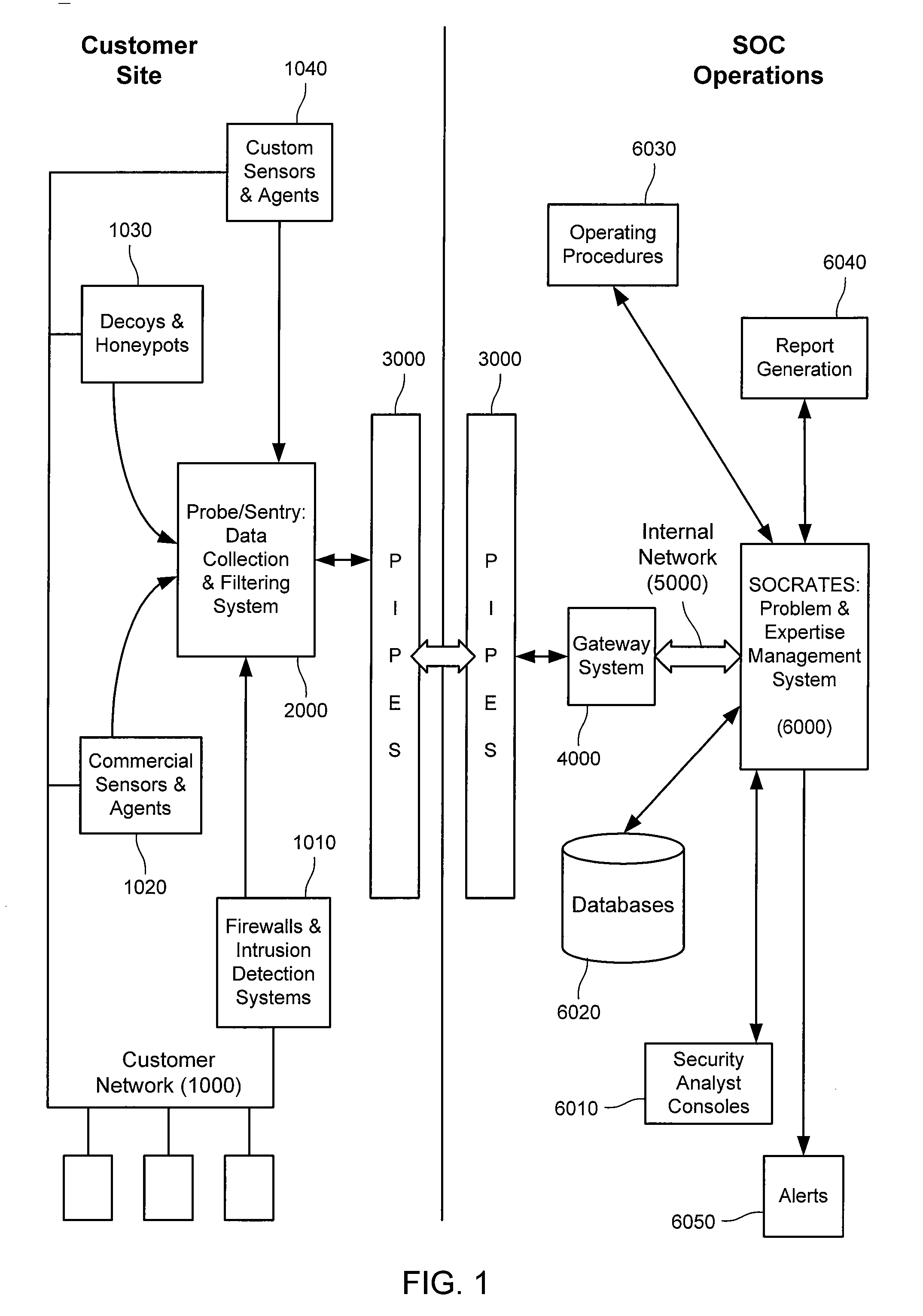
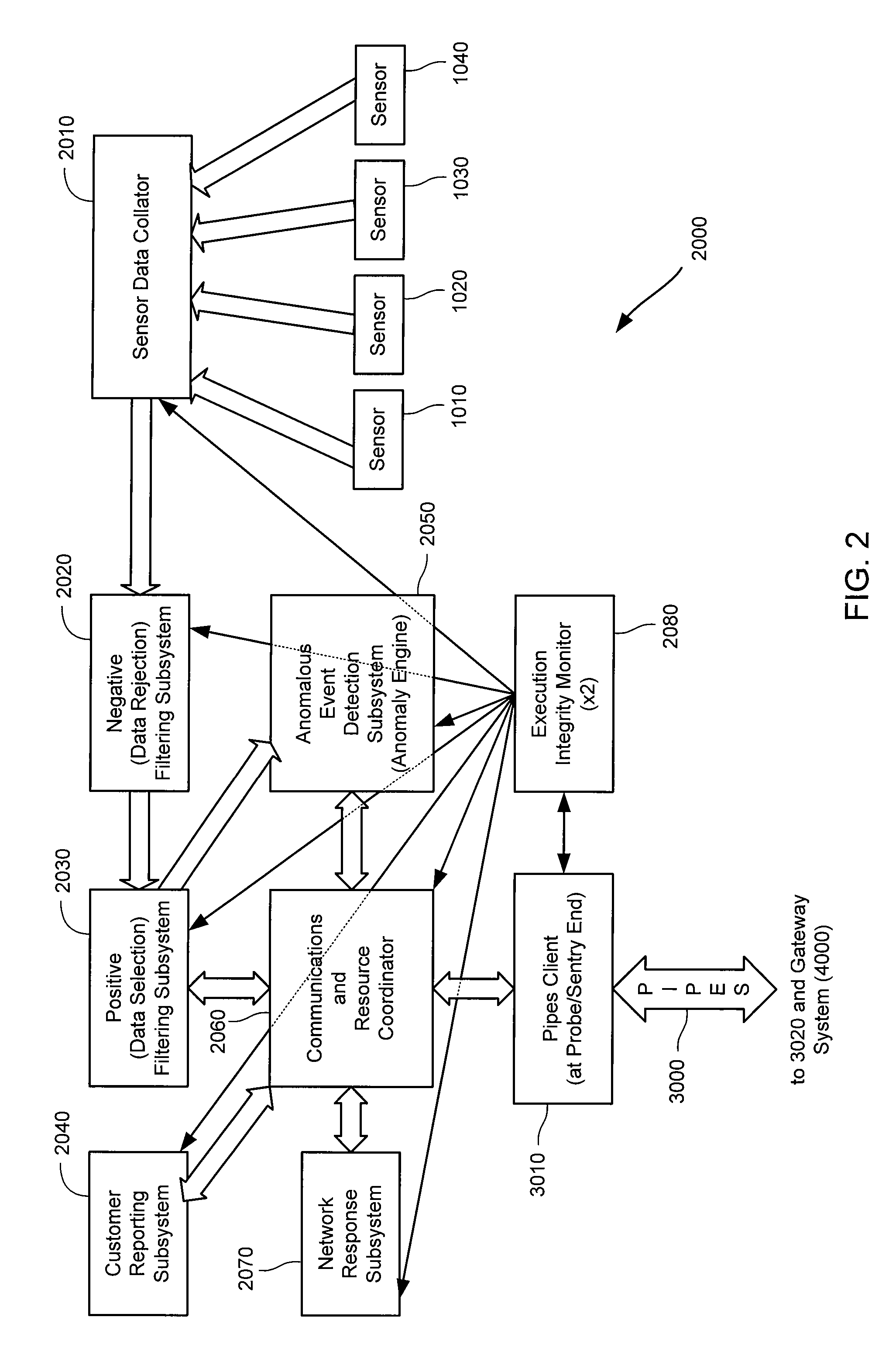
A probe attached to a customer's network collects status data and other audit information from monitored components of the network, looking for footprints or evidence of unauthorized intrusions or attacks. The probe filters and analyzes the collected data to identify potentially security-related events happening on the network. Identified events are transmitted to a human analyst for problem resolution. The analyst has access to a variety of databases (including security intelligence databases containing information about known vulnerabilities of particular network products and characteristics of various hacker tools, and problem resolution databases containing information relevant to possible approaches or solutions) to aid in problem resolution. The analyst may follow a predetermined escalation procedure in the event he or she is unable to resolve the problem without assistance from others. Various customer personnel can be alerted in a variety of ways depending on the nature of the problem and the status of its resolution. Feedback from problem resolution efforts can be used to update the knowledge base available to analysts for future attacks and to update the filtering and analysis capabilities of the probe and other systems.

Description

CROSS-REFERENCE TO RELATED APPLICATIONS [0001] This application is a continuation application of and claims priority from U.S. Non-Provisional patent application Ser. No. 09 / 766,343 filed Jan. 19, 2001 (Attorney Docket No. 022133-000510US) which claims priority from and is a non-provisional of U.S. Provisional Patent Application No. 60 / 190,326, filed Mar. 16, 2000 (Attorney Docket No. 022133-000500US), the entire disclosures of these applications are incorporated herein by reference for all purposes.FIELD OF THE INVENTION [0002] This invention relates generally to network security and, more specifically, to methods and systems for dynamic network intrusion monitoring, detection and response. BACKGROUND OF THE INVENTION [0003] Most computer and network security products focus on prevention. Firewalls prevent unauthorized traffic from entering a company's internal network; authentication mechanisms prevent unauthorized persons from logging on to a company's computers; and encryption p...

Claims


Application Information

Patent Timeline
Patent Type & Authority Applications(United States)
IPC IPC(8): G06F12/14G06F1/00G06F21/00H04L12/24H04L29/06
CPCG06F21/552H04L63/20H04L63/1416G06F2221/2101
Inventor SCHNEIER, BRUCEGROSS, ANDREW H.CALLAS, JONATHAN D.
Owner BT AMERICAS
Learn More