
Enclosed volume exhaust diffuser apparatus, system, and method

a technology of exhaust diffuser and enclosed volume, which is applied in the direction of mechanical apparatus, engine components, machines/engines, etc., can solve the problems of large cross-sectional area, high cost, and potential safety hazards, and achieve the effect of greater cross-sectional area

Active Publication Date: 2007-07-19
CUMMINS FILTRATION INC
View PDF33 Cites 30 Cited by
  • Summary
  • Abstract
  • Description
  • Claims
  • Application Information

AI Technical Summary

Benefits of technology

[0008] One way to deal with the problem would be to warn the operator of the vehicle or machine in which the engine and exhaust treatment system is installed of expelled exhaust temperatures reaching dangerous levels, enabling the operator to take steps to mitigate the situation, such steps potentially including moving the apparatus away from sensitive objects, initiating a cooling procedure, etc. This, however, would require detailed and expensive sensors and controls, would require operator intervention, and in any case the mitigation options for the operator would be relatively limited. If possible, it would be better that the exhaust gas be continually cooled before or as it leaves the tailpipe such that its temperatures never reach dangerous levels in the first place.
[0011] The present invention has been developed in response to the present state of the art, and in particular, in response to the problems and needs in the art that have not yet been fully solved by currently available systems. Accordingly, the present invention has been developed to provide an apparatus, system, and method for cooling exhaust gases that overcome many or all shortcomings in the art.

Problems solved by technology

This creates a potential safety hazard with regard to the heat flux of the gases leaving the tailpipe and creating discomfort or injury to humans, animals, or plants in proximity.
This, however, would require detailed and expensive sensors and controls, would require operator intervention, and in any case the mitigation options for the operator would be relatively limited.
The general problem of heat mitigation as the exhaust enters the atmosphere, however, is a relatively new one requiring novel approaches.
Some fire trucks (though not all) are equipped with a water spray device at the exhaust outlet for exhaust cooling, but such a scheme is limited to a situation where there is a ready water supply as well as experienced firefighters with hoses in hand rather than a single machine operator inexperienced in such situations.

Method used


Image

  • Enclosed volume exhaust diffuser apparatus, system, and method
  • Enclosed volume exhaust diffuser apparatus, system, and method
  • Enclosed volume exhaust diffuser apparatus, system, and method

Examples


Embodiment Construction

[0034] Reference throughout this specification to “one embodiment,”“an embodiment,” or similar language means that a particular feature, structure, or characteristic described in connection with the embodiment is included in at least one embodiment of the present invention. Appearances of the phrases “in one embodiment,”“in an embodiment,” and similar language throughout this specification may, but do not necessarily, all refer to the same embodiment.

[0035] The described features, structures, or characteristics of the invention may be combined in any suitable manner in one or more embodiments. In the following description, numerous specific details are provided to impart a thorough understanding of embodiments of the invention. One skilled in the relevant art will recognize, however, that the invention may be practiced without one or more of the specific details, or with other methods, components, materials, and so forth. In other instances, well-known structures, materials, or ope...


PUM


Abstract

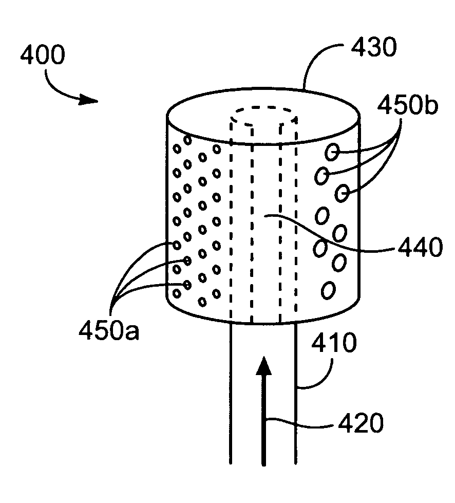
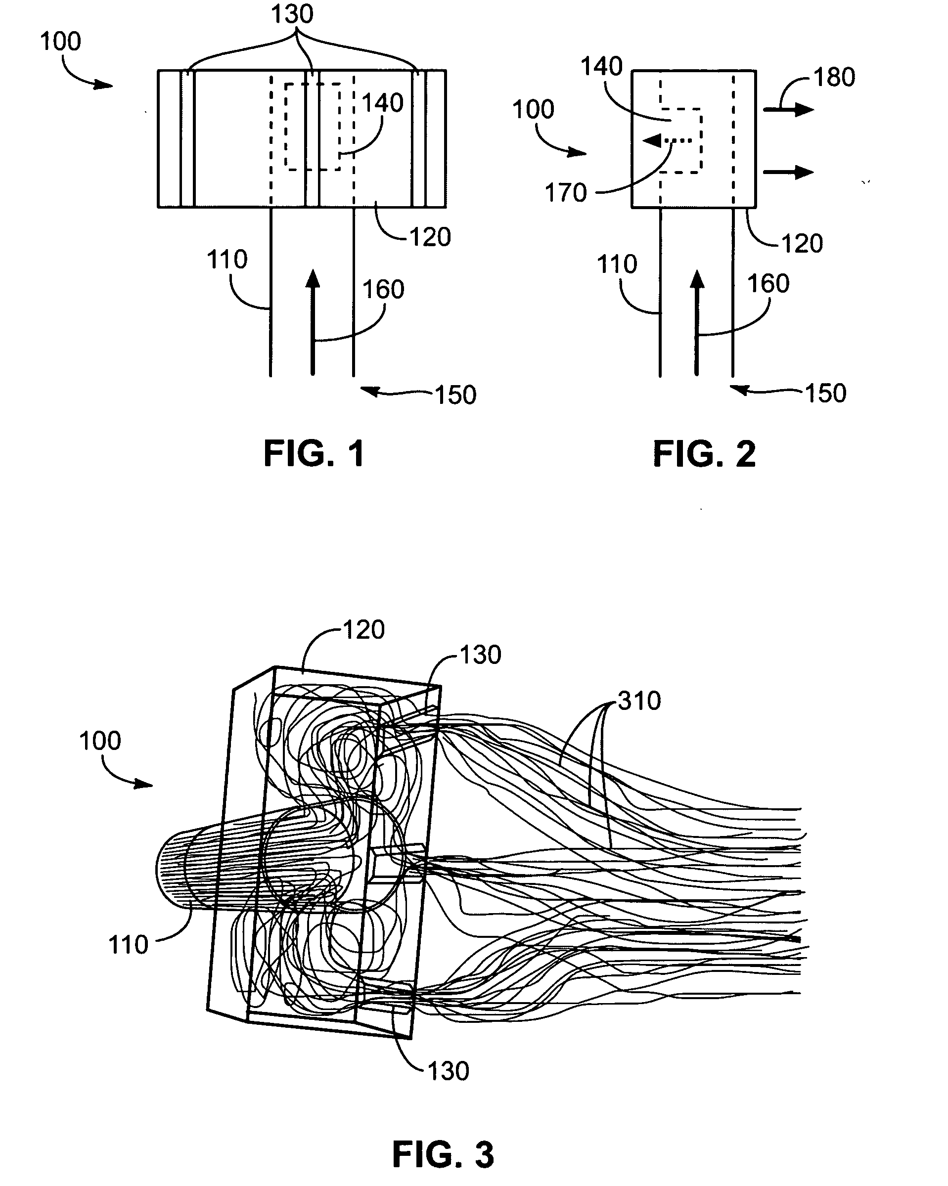
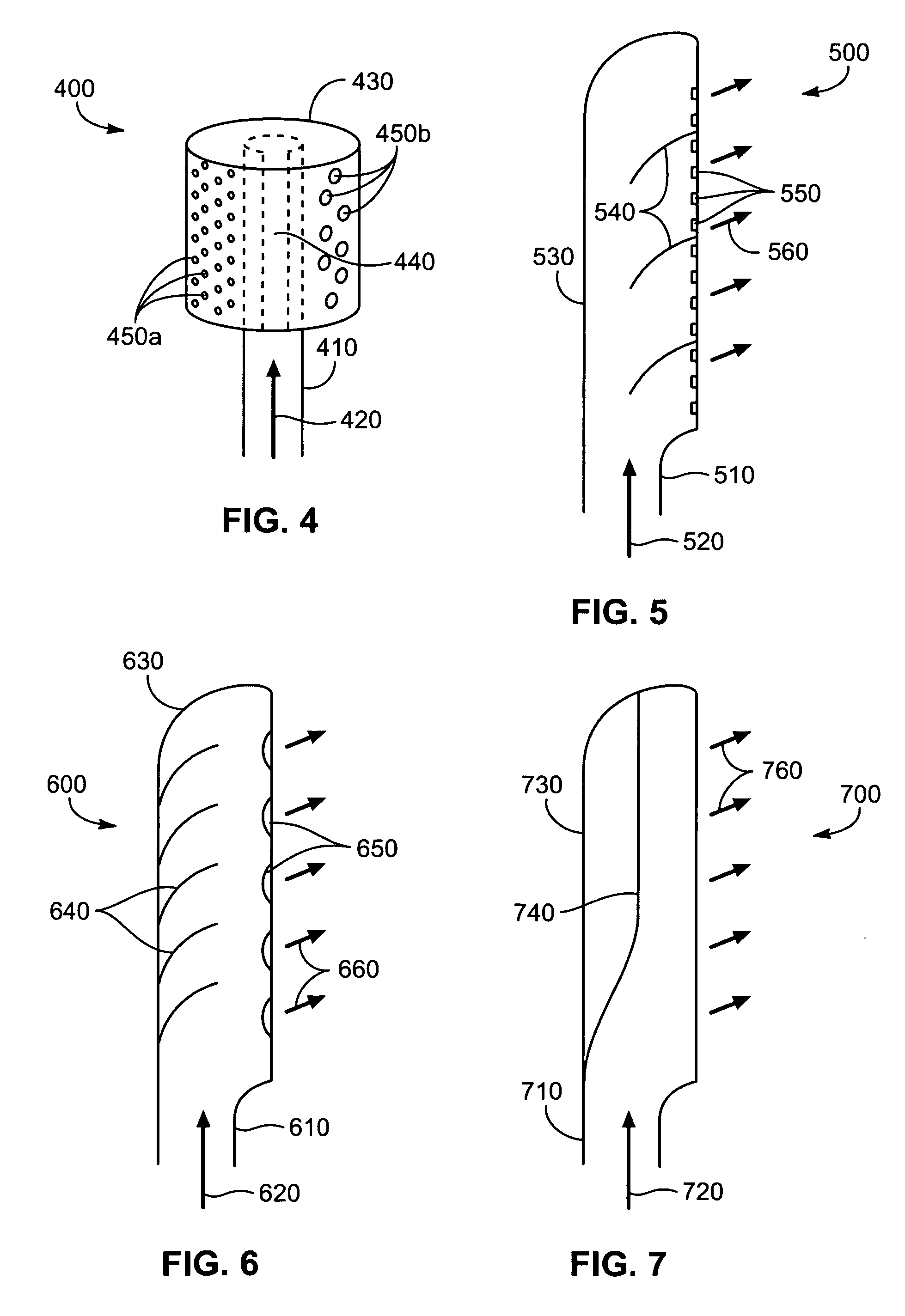
An apparatus, system, and method for cooling exhaust gases includes an inlet operatively connected to an exhaust port from a diesel engine or the like, and a housing defining a substantially enclosed volume. At least a portion of the volume is larger in cross-section than the inlet in cross-section, such that the exhaust gases expand upon entering the housing from the inlet. At least one outlet larger in collective cross-section than the inlet in cross-section is disposed on the housing and configured to expel the exhaust gases from the housing into the atmosphere.

Description

BACKGROUND OF THE INVENTION [0001] 1. Field of the Invention [0002] This invention relates to exhaust systems, and more particularly to apparatuses, systems, and methods for cooling exhaust gas as it leaves an enclosed exhaust stream. [0003] 2. Description of the Related Art [0004] This patent application is related to patent application Ser. No. <Ser. No. > titled “Lobed Exhaust Diffuser Apparatus, System, and Method,” filed on the same date as the present patent application, attorney docket No. 1900.2.14 and client docket No. 8-02-4805, and which is incorporated herein in its entirety. [0005] Environmental regulations are becoming increasingly strict with regard to engine exhaust emissions such as nitrogen oxides (NOx) and particulate matter. In the United States, the U.S. Environmental Protection Agency will begin enforcing new, more stringent, environmental regulations with regard to diesel engine particulate emissions in 2007, which has occasioned the need for diesel part...

Claims


Application Information

Patent Timeline
Patent Type & Authority Applications(United States)
IPC IPC(8): F01N3/00F01N13/08
CPCF01N2590/08F01N13/082
Inventor RYAN, MICHAEL E.DIXON, J. DAVIDKLEIN, PATRICK M.
Owner CUMMINS FILTRATION INC
Learn More