Bubble separator

Inactive Publication Date: 2007-07-19
TOYOTA BOSHOKU KK
View PDF3 Cites 45 Cited by
  • Summary
  • Abstract
  • Description
  • Claims
  • Application Information

AI Technical Summary

Benefits of technology

[0013]In view of the foregoing circumstances, it is an object of the present invention to provide a bubble separator that is capable of suppressing remixing after bubble separat

Problems solved by technology

However, in the dry sump system a considerable amount of air bubbles are mixed into the oil while it is being returned to the oil tank via the scavenger pump.
The bubbles contained in the oil are subsequently separated

Method used


Image

  • Bubble separator
  • Bubble separator
  • Bubble separator

Examples


first embodiment

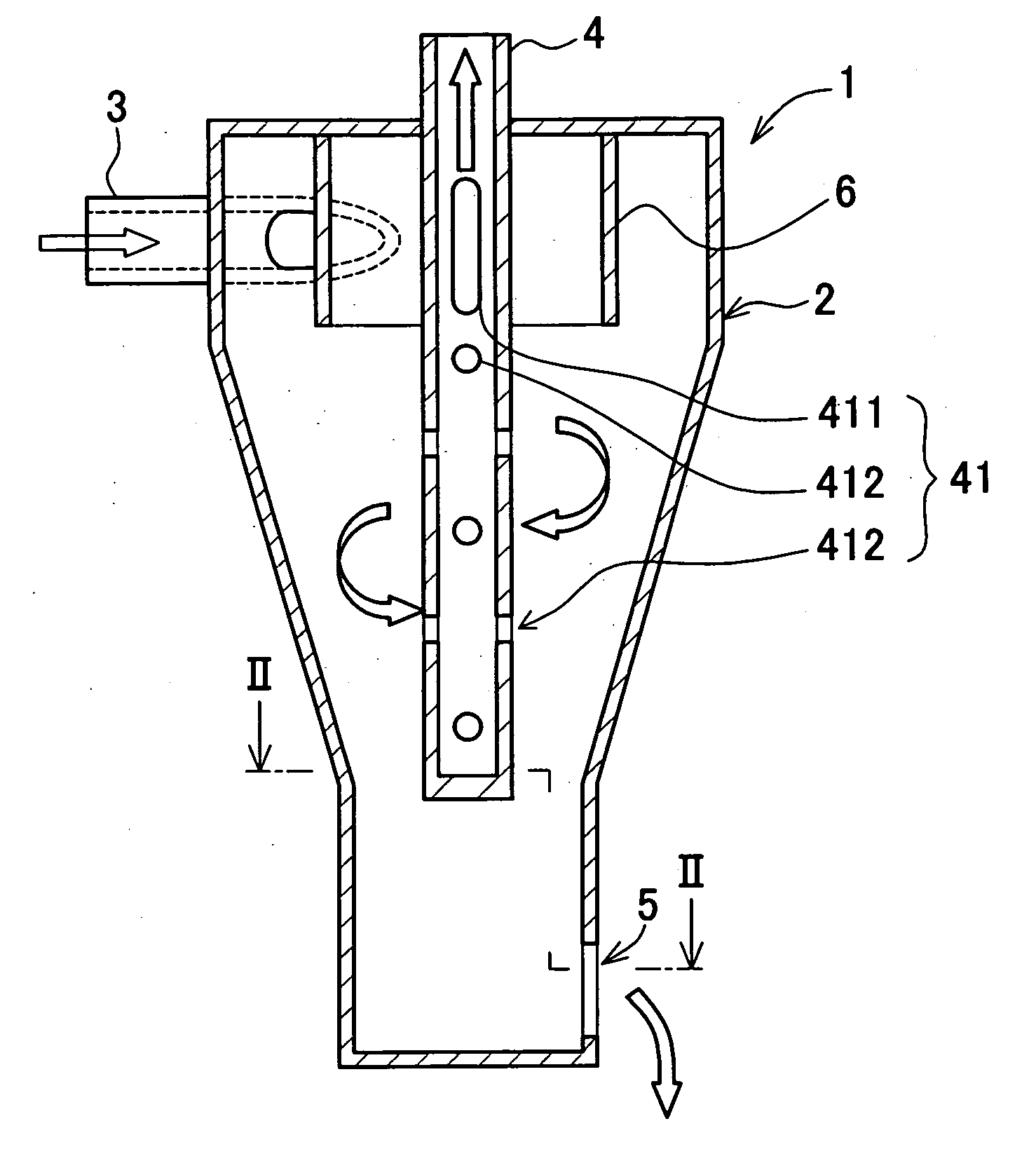
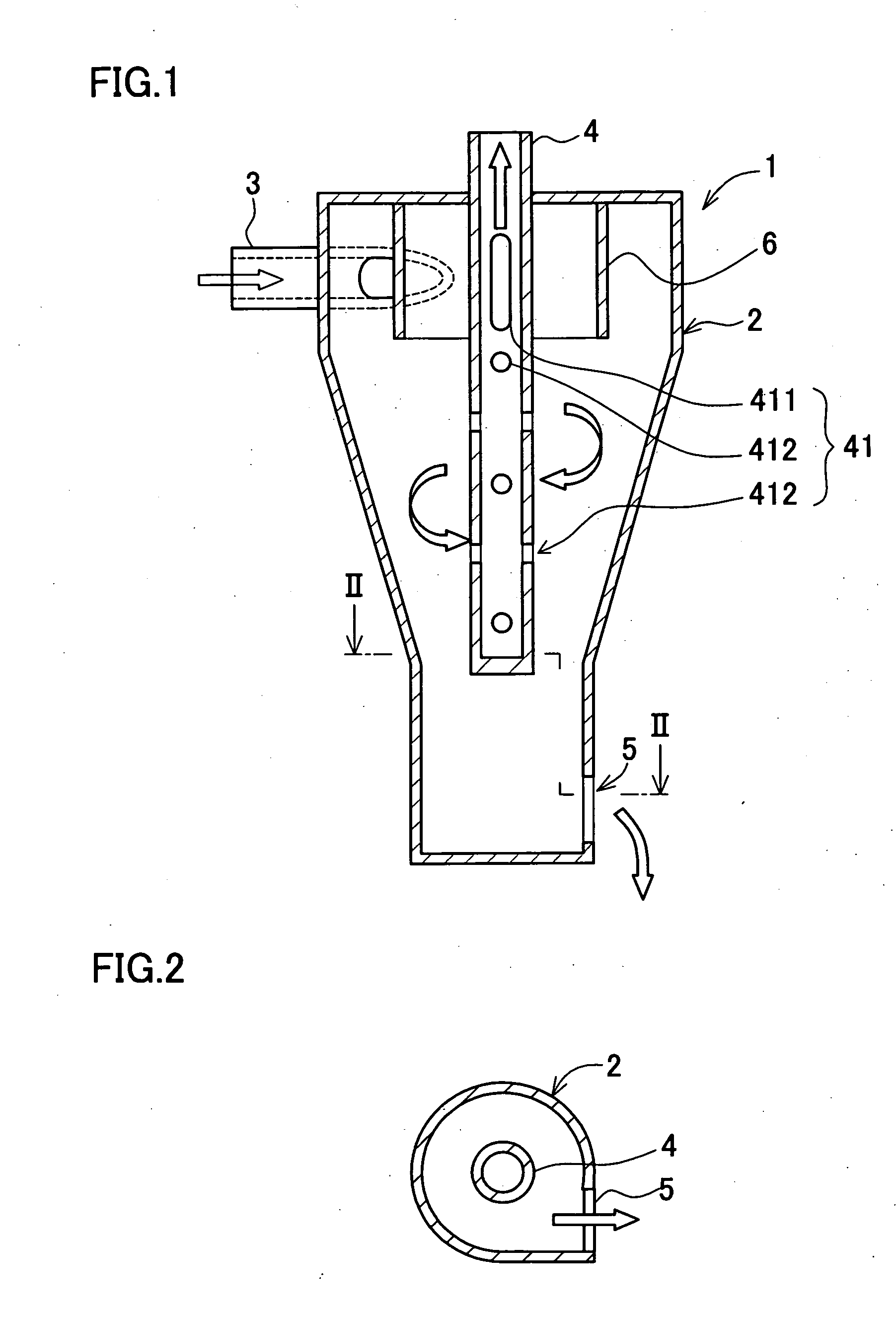
[0075]A bubble separator as shown in FIGS. 1 and 2, is used to eliminate bubbles, such as blow-by gas, that are included in bubble-containing oil, which is used by a lubrication system of an internal combustion engine for an automobile or the like. The bubble separator 1 has a body 2, an oil induction pipe 3 that acts as an oil induction portion, a gas discharge pipe 4 that acts as a gas discharge portion, and oil discharge hole 5 that acts as an oil discharge portion, and a upper partition 6.

[0076]The body 2 has a tapered cylindrical shape whose lower side becomes narrow.

[0077]The oil induction pipe 3 is provided on an upper portion of a peripheral wall of the body 2, and can introduce bubble-containing oil in a direction tangent to an inner periphery of the body 2.

[0078]The gas discharge pipe 4 is provided running through a general center of a ceiling portion of the body 2 and down to a lower side of the body 2. A discharge hole 41 is also provided for discharging separated bubbl...
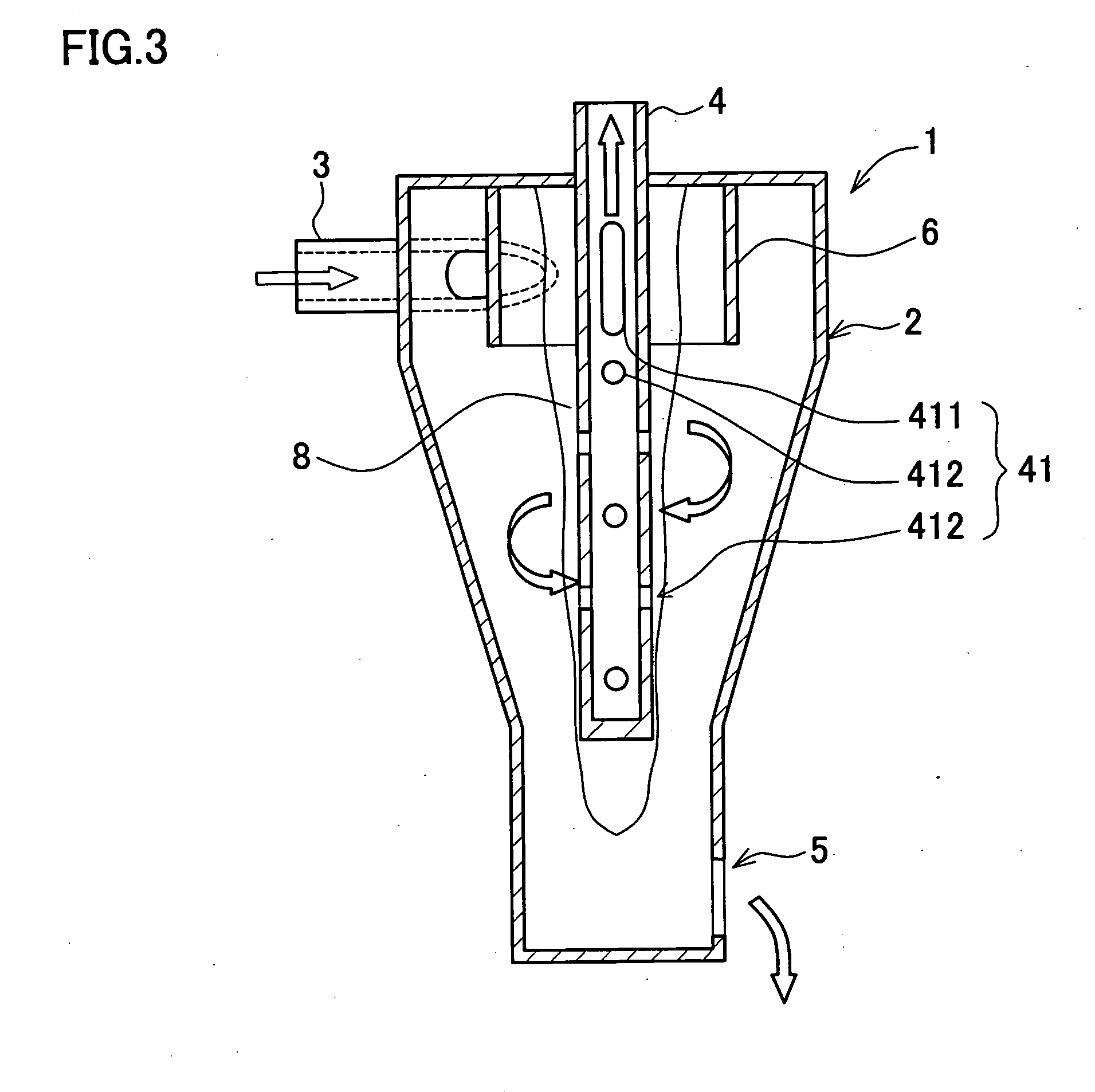
second embodiment

[0087]In the bubble separator 1A an interval at which a plurality of the lower discharge holes 412 is disposed progressively widens toward the lower side of the gas discharge pipe 4. Thus, the practical opening area progressively decreases toward the lower side of the gas discharge pipe 4. By disposing the lower discharge holes 412 in such a manner, more separated gas that is present in a greater amount toward the upper side can be removed. Therefore, the bubble separation efficiency can be increased.

[0088]It should be noted that the present invention is not limited to the above embodiments, and various modifications are possible within the scope of the present invention in accordance with the purpose and application. Namely, in the above embodiments, an “oil discharge portion” according to the present invention is configured from the oil discharge hole 5 that is provided extending from the peripheral surface of the body. However, the present invention is not limited by this, and o...


PUM

PropertyMeasurementUnit
Shapeaaaaaaaaaa
Areaaaaaaaaaaa
Partition functionaaaaaaaaaa

Abstract

A bubble separator includes a body with a generally cylindrical shape, an oil induction portion, a gas discharge portion with a generally cylindrical shape, an oil discharge portion, and an upper partition. The oil induction portion is provided on the body, and introduces bubble-containing oil to inside the body. The gas discharge portion is provided extending from a ceiling portion of the body, and discharges separated bubbles to outside the body. The oil discharge portion is provided on the body, and discharges separated oil to outside the body. The upper partition is provided extending from the ceiling portion, and is formed on a periphery of the gas discharge portion. According to the bubble separator of the present invention, the upper partition can prevent bubble-containing oil from directly blowing into the discharge hole of the gas discharge portion and discharging to outside the body together with separated gas.

Description

INCORPORATION BY REFERENCE[0001]The disclosure of Japanese Patent Application No. 2006-007880 filed on Jan. 16, 2006 including the specification, drawings and abstract is incorporated herein by reference in its entirety.BACKGROUND OF THE INVENTION[0002]1. Field of the Invention[0003]The present invention relates to a bubble separator. More specifically, the present invention relates to a bubble separator that is capable of suppressing remixing after bubble separation, and is particularly capable of performing bubble separation with a high bubble separation efficiency for oil used in a lubrication system for an internal combustion engine.[0004]2. Description of the Related Art[0005]Dry sump and wet sump systems are commonly known as modes for lubricating internal combustion engines. The dry sump system is a type in which engine oil collects in an oil tank and the engine oil is sent under pressure from the oil tank through a feed pump to lubricate respective parts of the engine. Oil t...

Claims


Application Information

Patent Timeline
IPC IPC(8): B01D19/00
CPCB01D19/0057F01M2001/1078B04C5/14F01M2013/0427B04C5/13F01M2011/007
Inventor SAITO, YASUHIROTAKAHARA, TOSHIHIRO
Owner TOYOTA BOSHOKU KK
Why Eureka
Try Eureka