Grill

a grill and grill body technology, applied in the field of grills, can solve the problems of increased lighting, increased heat generation, and increased operating costs of the grill operator, and achieve the effect of reducing the amount of light available for the operator, increasing the operating cost, and increasing the operating cos

Inactive Publication Date: 2007-07-19
BLACK & DECKER INC
View PDF15 Cites 70 Cited by
  • Summary
  • Abstract
  • Description
  • Claims
  • Application Information

AI Technical Summary

Benefits of technology

[0010] In yet another form, the present teachings provide a grill having a housing, a first lid, a second lid and a light assembly. The housing defines a first chamber and a second chamber that is disposed above the first chamber. The first lid is pivotally coupled to the housing and is moveable between a first position, which closes the first chamber to inhibit access thereto, and a second position, which at least partially clears the first chamber to permit access thereto. The second lid is pivotally coupled to the housing and is moveable between a first position, which closes the second chamber to inhibit access thereto, and a second position, which at least partially clears the second chamber to permit access thereto. The second lid has a sidewall that is generally transverse to an axis about which the second lid pivots. The handle assembly is coupled to second lid and includes a handle, a wire harness, a light source and a switch. The handle is coupled to the sidewall and extends away from the first chamber. The wire harness is adapted to electrically couple the light source to the switch and a source of electrical power. The light source is coupled to a second lid. The switch is configured to selectively couple the light source to the source of electrical power. Light generated by the light source illuminates the first chamber when the first lid is positioned in the open position.

Problems solved by technology

One drawback concerns the amount of light that is available for the grill operator to see the food that is being cooked on the cooking grid.
This solution, however, relies on ambient light for illumination of the cooking chamber and moreover provides no additional lighting when the lid is placed in an open condition.
This solution is disadvantageous in that the handle for moving the lid is placed directly over the cooking grid when the lid is open and can therefore become relatively hot to the touch.
Another drawback is related to gas-fired grills having a removable source of gaseous fuel (e.g., a propane tank).
As current regulations limit the amount by which the tank may move when mounted to the grill, the known fuel tank gages tend to be hard to read and / or to be positioned in a location where the fuel level indication is not conspicuous.

Method used


Image

  • Grill
  • Grill
  • Grill

Examples


Embodiment Construction

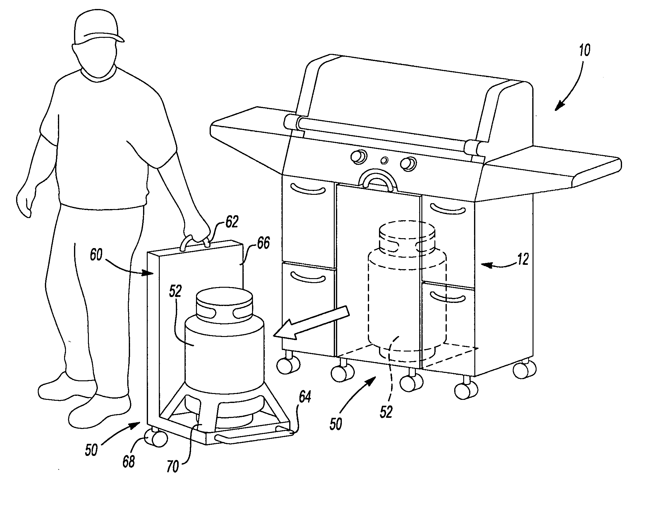
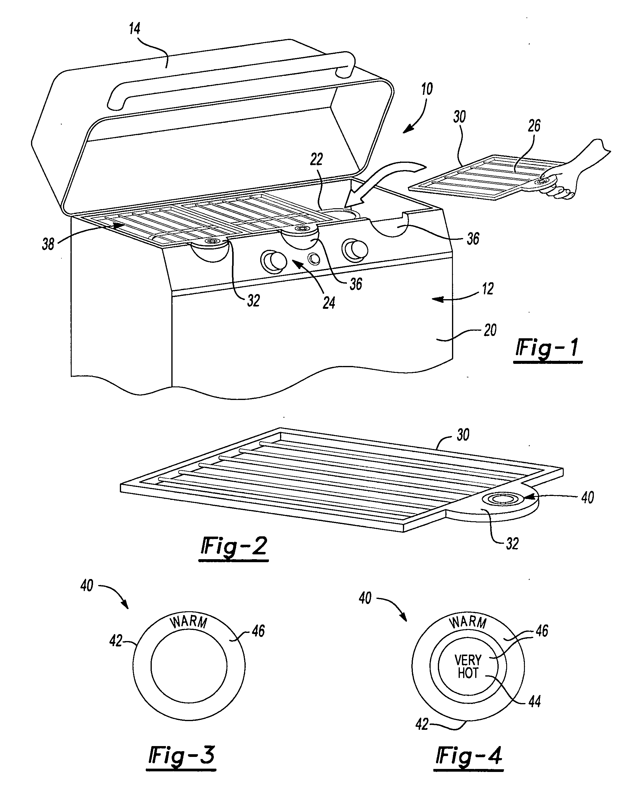
[0046] With reference to FIG. 1 of the drawings, a gas-fired grill constructed in accordance with the teachings of the present invention is generally indicated by reference numeral 10. The grill 10 may include a base 12 and a lid 14 that may be pivotally coupled to the base 12. The base 12 may include a housing 20, one or more burners 22, a control set 24 and a plurality of grates 26 that are supported by the housing 20 at a location above the burners 22. The control set 24 is coupled to a source of fuel, such as liquefied petroleum or natural gas, and may regulate the delivery of the fuel to the burners 22 in a known manner.

[0047] The grates 26, which may be dishwasher safe for ease of cleaning, include a frame member 30 and a handle 32 that may be coupled to the frame member 30 and employed by the user as a means for lifting the grate 26. In the example illustrated, the handle 32 extends into a well 36 that is formed in the housing 20 when the grate 26 is positioned on the base 1...


PUM


Abstract

A grill, such as a gas-fired grill, can employ a light assembly for illuminating a cooking area and/or a fuel gage that can be more readily and accurately read to determine an amount of fuel in a fuel tank. The light assembly includes a light source, which is mounted to an upper one of two discrete lids. The light source can be selectively illuminated via a switch. The switch may be coupled to a handle that is employed to open and close the second lid. The handle can be coupled to a side of the lid so as to position the switch in a location that can be relatively cool. The fuel gage can employ a pivoting platform, the motion of which may be employed to determine an amount of fuel in the fuel tank.

Description

CROSS-REFERENCE TO RELATED APPLICATIONS [0001] This application is a continuation of International Application PCT / US2005 / 024036 filed Jul. 7, 2005, which claims the benefit of U.S. Provisional Patent Application Ser. No. 60 / 586,118 entitled “Gas Grill” and filed Jul. 7, 2004.INTRODUCTION [0002] The present invention generally relates to outdoor cooking equipment and more particularly to a grill such as a gas-fired grill. [0003] Grills, and in particular portable gas-fired grills, have become very popular as outdoor cooking devices. Portable gas grills generally consist of a cooking chamber supported by a support frame that may or may not have wheels. The cooking chamber generally includes gas burners, which are located in the lower portion of the cooking chamber, and a cooking grid that is spaced a distance above the gas burners for supporting the food to be cooked. A source of gaseous fuel, such as a fuel tank containing a liquid fuel (e.g., liquid propane), is coupled to the gas ...

Claims


Application Information

Patent Timeline
Patent Type & Authority Applications(United States)
IPC IPC(8): F24C15/12F24C15/00F24C3/02F24C3/00
CPCA47J37/0682A47J37/0713A47J37/0786F24C15/16A47J2202/00F24C3/14A47J43/18F24C3/027
Inventor MURRAY, CHRISTOPHER J.AGRONIN, MICHAEL L.
Owner BLACK & DECKER INC
Why Eureka
Try Eureka