
Flat plate heat transfer device and method for manufacturing the same

a heat transfer device and flat plate technology, applied in semiconductor devices, lighting and heating apparatus, cooling/ventilation/heating modifications, etc., can solve the problems of increasing energy consumption, difficult to form a plurality of such small and fine capillary channels through extrusion, and difficult to have a sufficient vapor dispersion channel, etc., to achieve effective heat transfer and prevent device distortion

Inactive Publication Date: 2007-07-19
LS MTRON LTD
View PDF13 Cites 45 Cited by
  • Summary
  • Abstract
  • Description
  • Claims
  • Application Information

AI Technical Summary

Benefits of technology

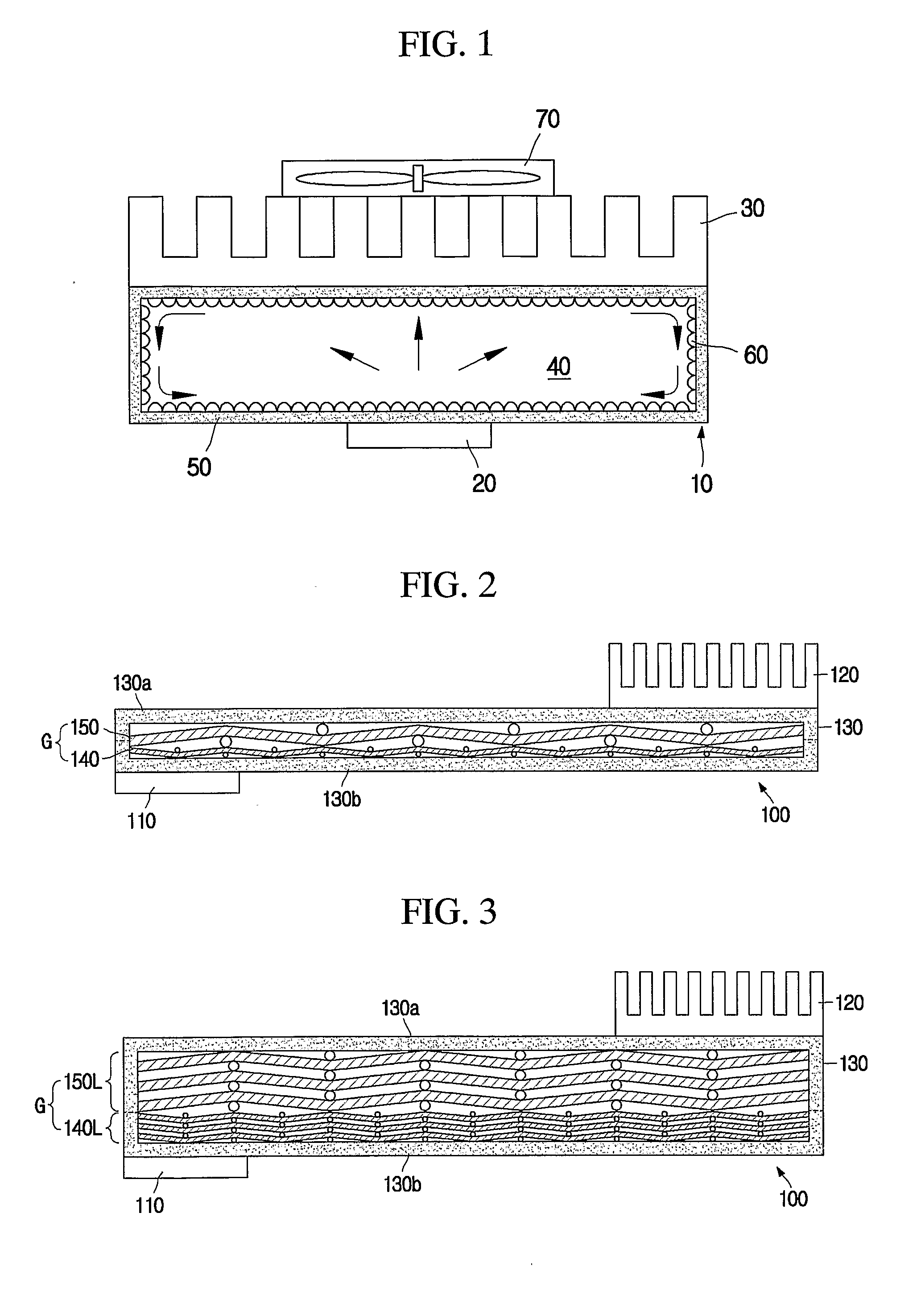
[0009] The present invention is designed to solve the problems of the prior art, and therefore it is an object of the present invention to provide an improved flat plate heat transfer device with a geometric structure that is capable of preventing distortion of the device to ensure reliability of product by firmly supporting a flat case of the flat plate heat transfer device that becomes thinner, and also giving a vapor dispersion channel and a liquid flow channel in an optimized direction for effective heat transfer.

Problems solved by technology

In addition, together with the increased demands for higher responsiveness of an electronic equipment and improvement of functions, energy consumption is also tending increased.
However, forming a plurality of such small and fine capillary channels by means of extrusion is very difficult.
However, it is not easy to have a sufficient vapor dispersion channel in the flat case of the flat plate heat transfer device with small thickness.
In particular, since the flat case is kept in a vacuous state (or, a decompressed state), the upper and lower plates of the case are apt to be crushed or distorted during its manufacturing procedure, thereby deteriorating reliability of the product.

Method used


Image

  • Flat plate heat transfer device and method for manufacturing the same
  • Flat plate heat transfer device and method for manufacturing the same
  • Flat plate heat transfer device and method for manufacturing the same

Examples


experimental example

[0098] Inventors prepared upper and lower plates of a flat case as shown in FIG. 15 with the use of an electrolytic copper foil with a thickness of 0.1 mm, and then mounted a mesh aggregate, which is configured so that one coarse mesh is interposed between two fine meshes as shown in FIG. 17, in the flat case so as to make three types of flat plate heat transfer devices as shown in the following table 1.

TABLE 1Coarse MeshFine MeshType 1 (sample 1)Main directionSub-directionType 2 (sample 2)Main directionMain directionType 3 (sample 3)Sub-directionMain direction

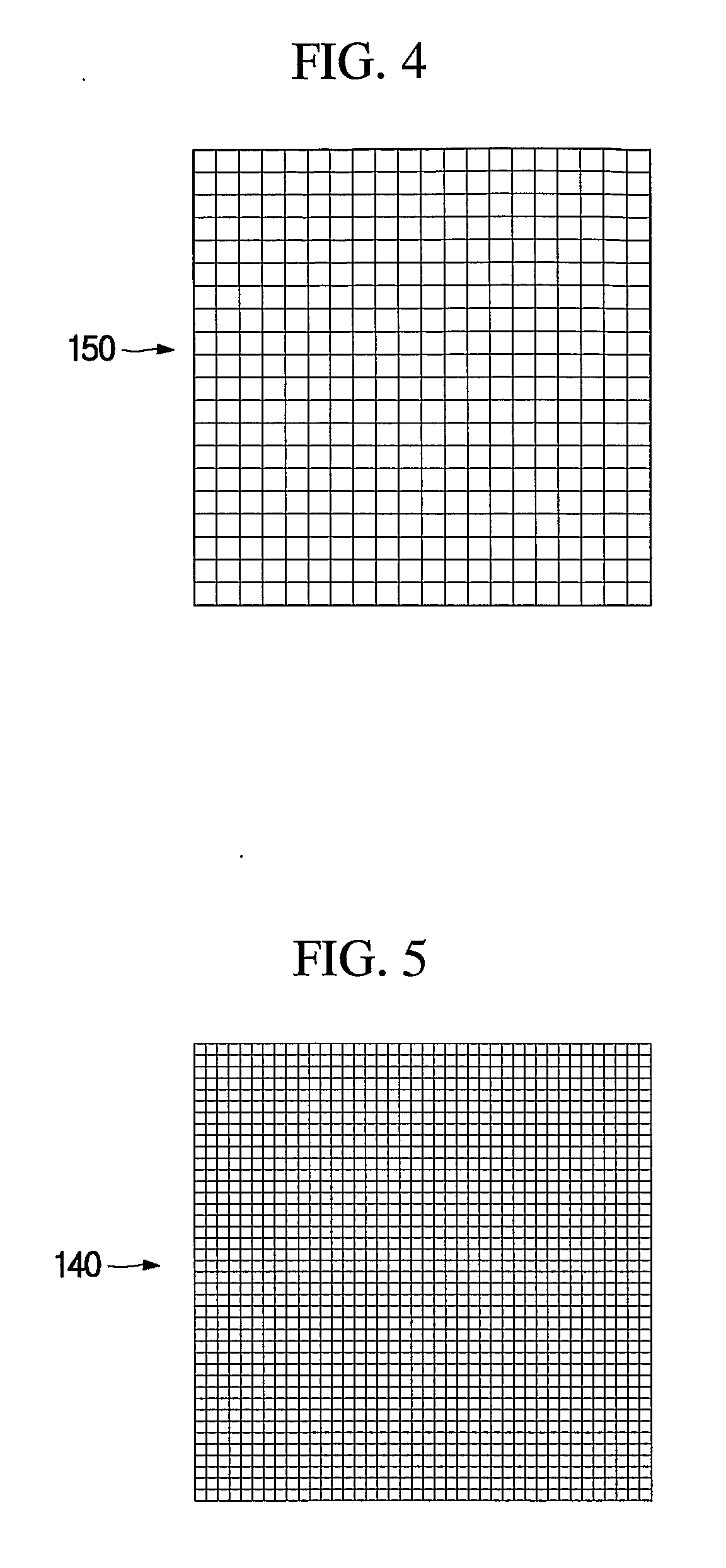
[0099] The samples 1, 2 and 3 were respectively 120 mm, 50 mm and 1.3 mm in width, length and height, and the mesh used is a copper screen mesh in which a content of copper is at least 99%. The coarse mesh had a wire diameter d of 0.225 mm, a mesh thickness of 0.41 mm and a mesh number of 15, while the fine mesh layer had a wire diameter d of 0.11 mm, a thickness of 0.22 mm and a mesh number of 100. The upper and lower plate...


PUM


Abstract

A flat plate heat transfer device contacted with heat source and heat-emitting unit at both end transfers heat generated at the heat source to the heat-emitting unit horizontally. The device includes a thermally-conductive flat case containing a working fluid evaporated with absorbing heat from the heat source and condensed with emitting heat to the heat-emitting unit; and a mesh aggregate installed in the case so that coarse and fine meshes in which wires are woven to be alternately crossed up / down are vertically laminated in contact. The coarse mesh gives main-directional and sub-directional vapor dispersion channels with different sectional areas at each crossing point of the mesh wires for vapor to flow therethrough. The main-directional vapor dispersion channel with relatively larger sectional area is parallel to heat transfer direction. The fine mesh gives liquid flow channels along running direction of the mesh wire from each crossing point of the mesh wires.

Description

TECHNICAL FIELD [0001] The present invention relates to a flat plate heat transfer device capable of emitting heat from a heat source by circulating a working fluid using evaporation and condensation and its manufacturing method, and more particularly to a flat plate heat transfer device capable of preventing crush of a flat case and giving vapor dispersion channels and liquid flow channels in a direction that ensures a maximum heat transfer efficiency and its manufacturing method. BACKGROUND ART [0002] In recent, an electronic equipment such as notebook or PDA becomes smaller and thinner along with the development of integration technique. In addition, together with the increased demands for higher responsiveness of an electronic equipment and improvement of functions, energy consumption is also tending increased. Accordingly, much heat is generated from electronic components in the electronic equipment while the equipment is operated, so various flat plate heat transfer devices ar...

Claims


Application Information

Patent Timeline
IPC IPC(8): F28D15/00H01L23/427H05K7/20
CPCH01L23/427H01L2924/0002H01L2924/00H05K7/20
Inventor KIM, HYUN-TAELEE, YONG-DUCKOH, MIN-JUNGJANG, SUNG-WOOK
Owner LS MTRON LTD
Learn More