Classifier for granular material

a technology of granular materials and classifiers, applied in the direction of reverse direction vortex, solid separation, sorting, etc., can solve the problems of large volume of whole installation and complex design, and achieve the effect of minimising turbulen

Active Publication Date: 2007-07-19
MAGOTTEAUX INT SA
View PDF8 Cites 2 Cited by
  • Summary
  • Abstract
  • Description
  • Claims
  • Application Information

AI Technical Summary

Benefits of technology

[0024] The classifier of the invention is also characterised by the presence of one or several deflectors 7 that are conical, cylindrical or radial (angled or straight) on top of the bottom of the recovery chamber 2, outside the air-extraction duct 3, so as to minimise the turbulence near the bottom of the chamber and to avoid that the material is picked up again by the air.

Problems solved by technology

The whole installation proves relatively bulky and of quite complex design.

Method used


Image

  • Classifier for granular material
  • Classifier for granular material
  • Classifier for granular material

Examples


Embodiment Construction

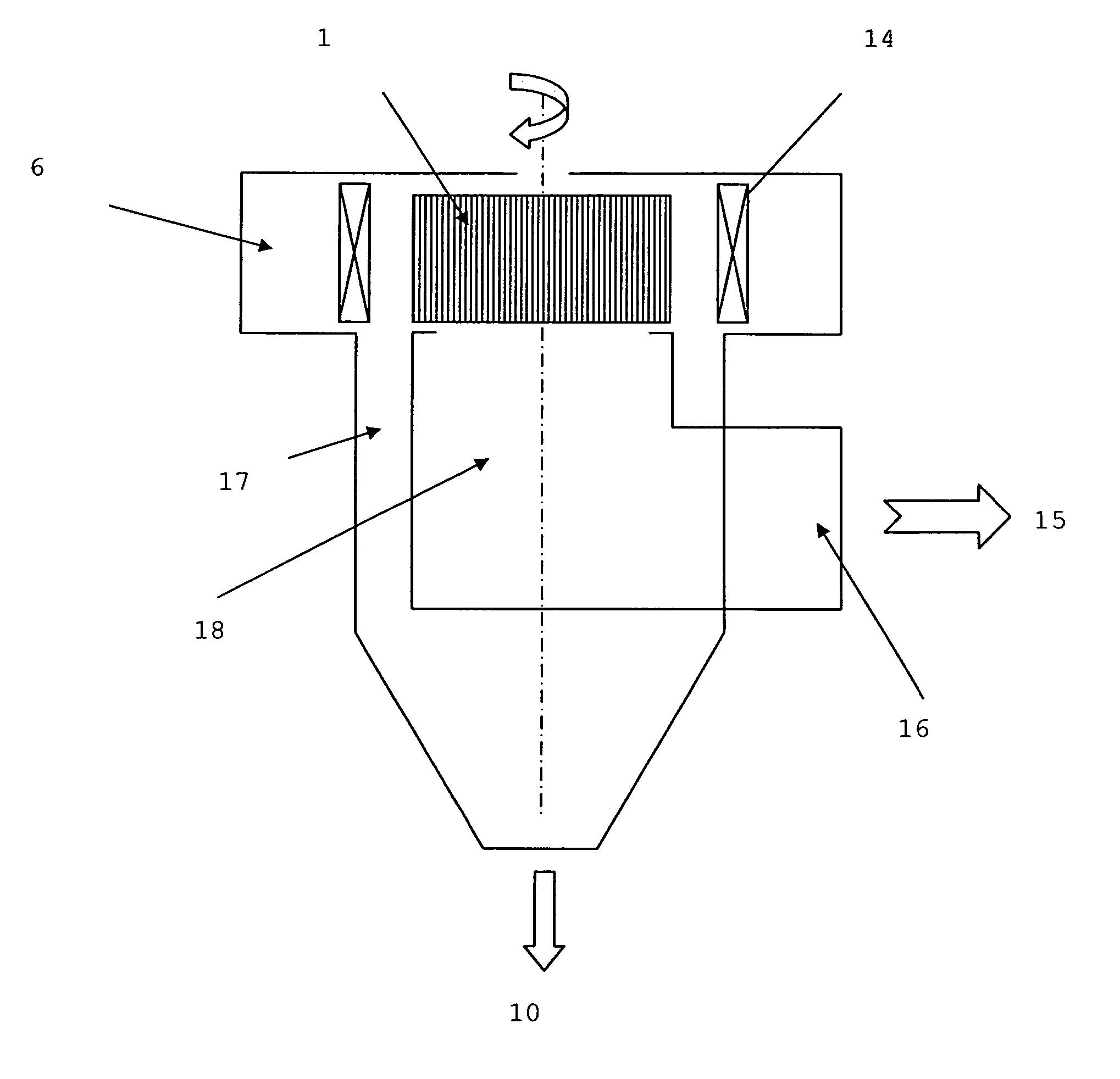
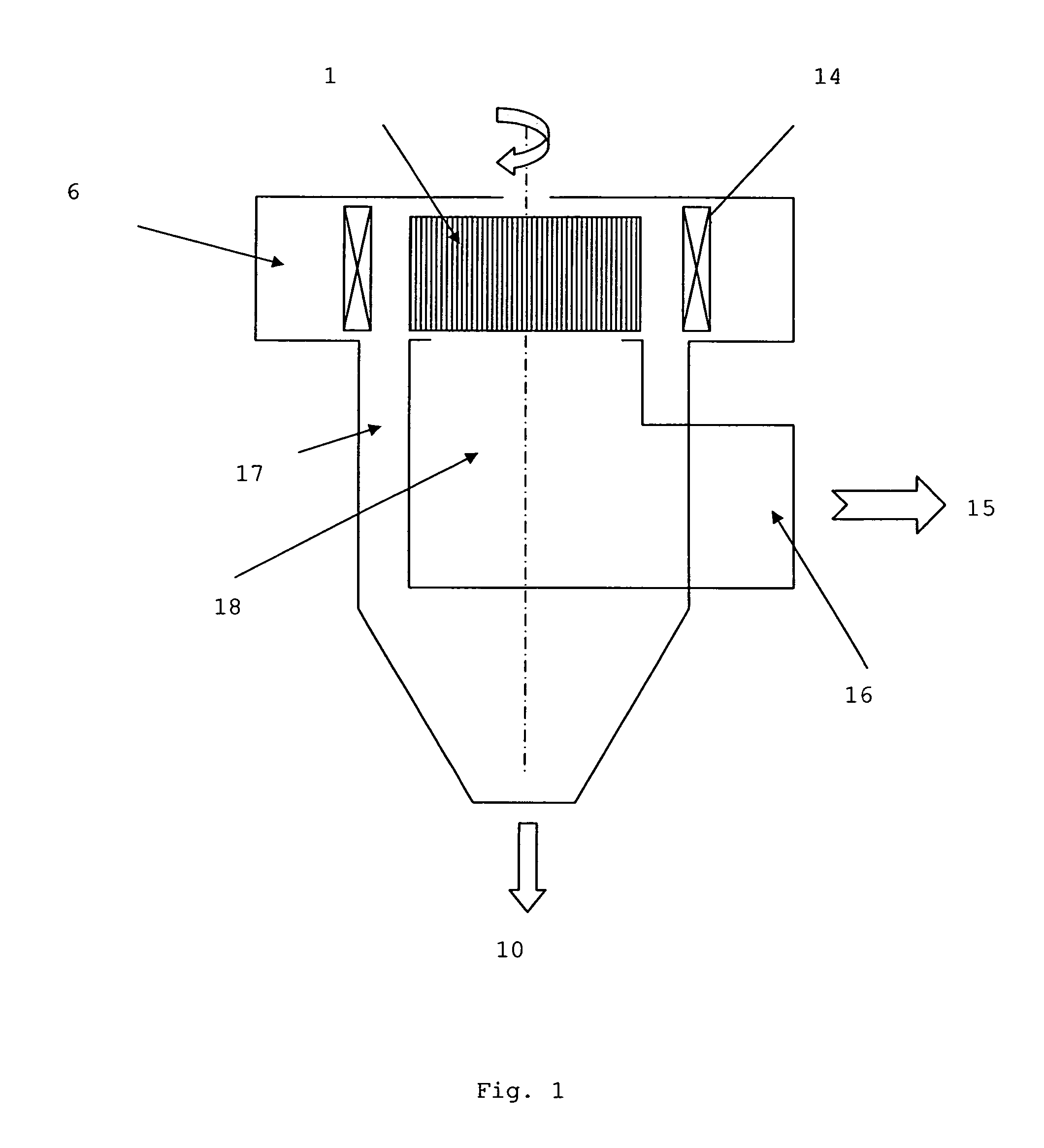
[0036] All types of classifier operate according to the same principle, which is shown in FIG. 1. The heart of the classifier comprises a squirrel cage 1 rotating about a vertical axis. This cage comprises spaced plates or bars and is surrounded by vanes 14 allowing to direct the air before it enters through the intake volute 6 in the cage 1. Vanes 14 may also assist with controlling the airflow.

[0037] The material to be separated enters the sorting zone defined by the outside of the cage 1 and the deflectors 4. The maximum size of the particles entering the cage with the air will be determined by the rotation velocity of the cage 1 and the volume of air with which the classifier is fed.

[0038] The larger particles remain outside the cage and are collected in the refuse chamber 17. These large particles come out of the classifier by gravity 10. The air charged with fine particles 15 comes out of the cage either through the top or laterally and it leaves the classifier by a duct. Th...


PUM


Abstract

The present invention relates to a dynamic air classifier for the separation of granular and powdery materials into fractions of different grain sizes comprising a rotary cage, wherein: said classifier also comprises a recovery chamber for fine materials with a outlet bottom, said chamber being defined by a casing; said recovery chamber is coaxially arranged in the protrusion of the rotary cage so as to be able to use the vortex created by the rotary cage for cycloning said material; said recovery chamber comprises openings in the casing allowing the passage of the centrifuged material towards ducts for collecting the material located outside the chamber.

Description

FIELD OF THE INVENTION [0001] The present invention relates to the separation of granular materials, and in particular to the classification of powders or similar materials by means of a dynamic air classifiers. STATE OF THE ART [0002] The separation of granular and powdery materials into two fractions with different grain sizes may be achieved by means of dynamic air classifiers. The materials concerned are powders with particle sizes of up to 1,000 μm such as cement, limestone or lime, ore and coal dust, among others. [0003] The capacities of material treated vary from a few tonnes to several hundreds of tonnes per hour. [0004] Dynamic classifiers have undergone several major changes allowing to classify them into three large groups. The first generation, generally known by the names of “turbo,”“heyd” or “whirlwind”, has been improved by the second generation of the “wedag” type. [0005] The 3rd generation is the most effective from the point of view of the separation efficiency. T...

Claims


Application Information

Patent Timeline
Patent Type & Authority Applications(United States)
IPC IPC(8): B07B7/00B07B7/04B07C7/04B07B4/00B07B7/083
CPCB07B7/083
Inventor PRIGNON, XAVIER
Owner MAGOTTEAUX INT SA
Why Eureka
Try Eureka