Autorotation flight control system

a flight control and automatic flight technology, applied in the field of automatic flight control systems, can solve the problems of triggering complete engine failures from the simulator operator's station, affecting the operation of instruments, process and machine control, and affecting the effect of personal actuation, so as to achieve the effect of high degree of control consistency and accuracy, and easy manipulation

Active Publication Date: 2007-07-19
SUBARU TECNICA INTERNATIONAL
View PDF4 Cites 86 Cited by
  • Summary
  • Abstract
  • Description
  • Claims
  • Application Information

AI Technical Summary

Benefits of technology

[0024] In one aspect the present invention comprises the application of a real-time trajectory optimization method for guiding a manned rotorcraft, an autonomous unmanned rotorcraft, or a remote operator of an unmanned rotorcraft, through an autorotation in the event of partial or total loss of power. The invention provides for safe landing of such a rotorcraft. Further, successful autorotations may be performed from well within the manufacturer's designated unsafe operating area of the height-velocity profile of a rotorcraft or helicopter by employing the fast and robust optimal algorithm of the present invention. The invention applies nonlinear constrained optimal control theory to solve for a vehicle's trajectory and the required control inputs to accomplish a successful autorotation. The guidance algorithm of the present invention generates optimal trajectories and control commands via the direct-collocation optimization method, solved using a commercially available nonlinear programming problem solver. The control inputs computed by optimal control formulation are collective pitch and aircraft pitch, which are easily manipulated by an onboard or remote pilot or converted to collective and longitudinal cyclic commands in the case of an autonomous unmanned rotorcraft. The formulation of the op

Problems solved by technology

Complete engine failures could be triggered from the simulator operator's station at any time.
Engine failures r

Method used


Image

  • Autorotation flight control system
  • Autorotation flight control system
  • Autorotation flight control system

Examples


Embodiment Construction

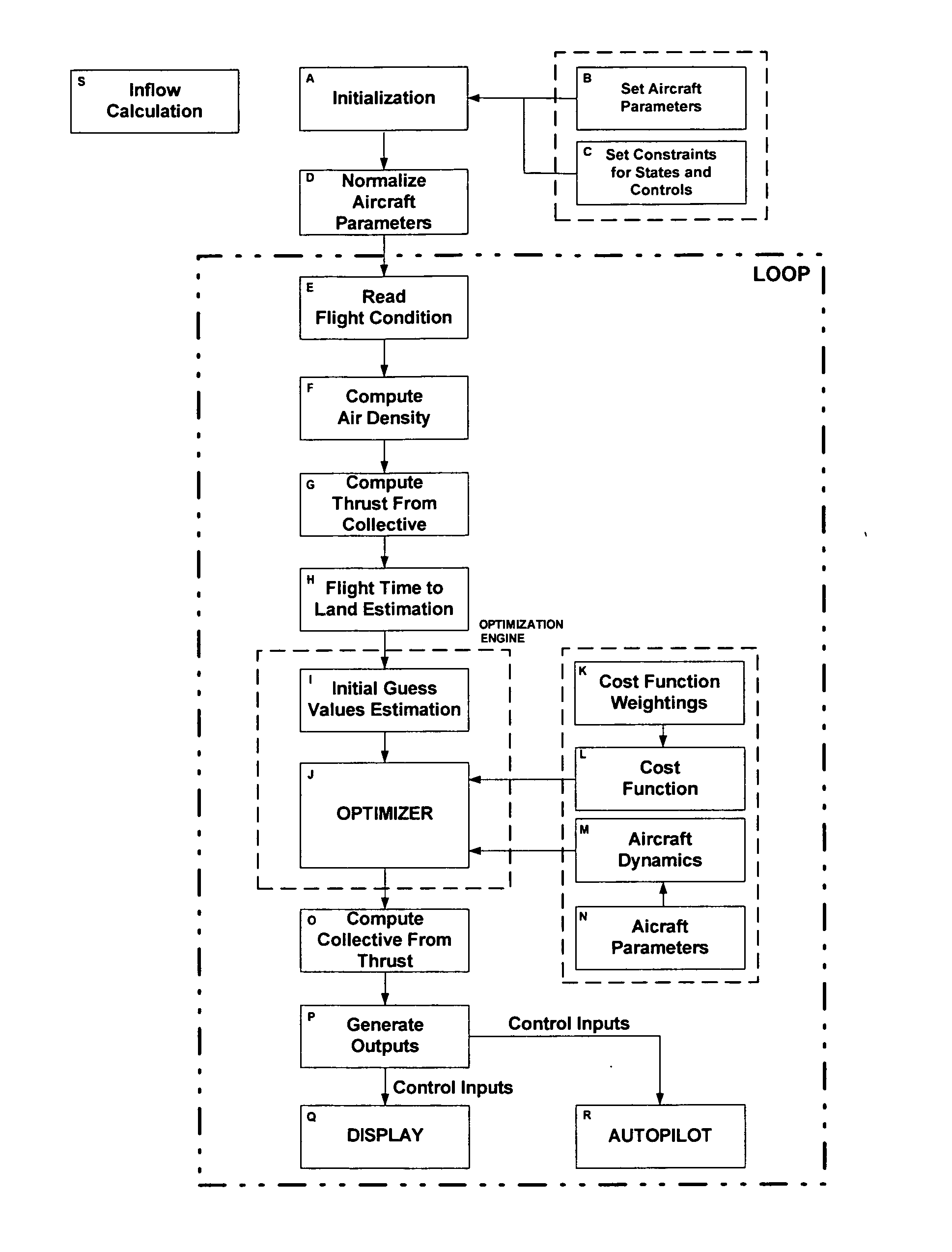
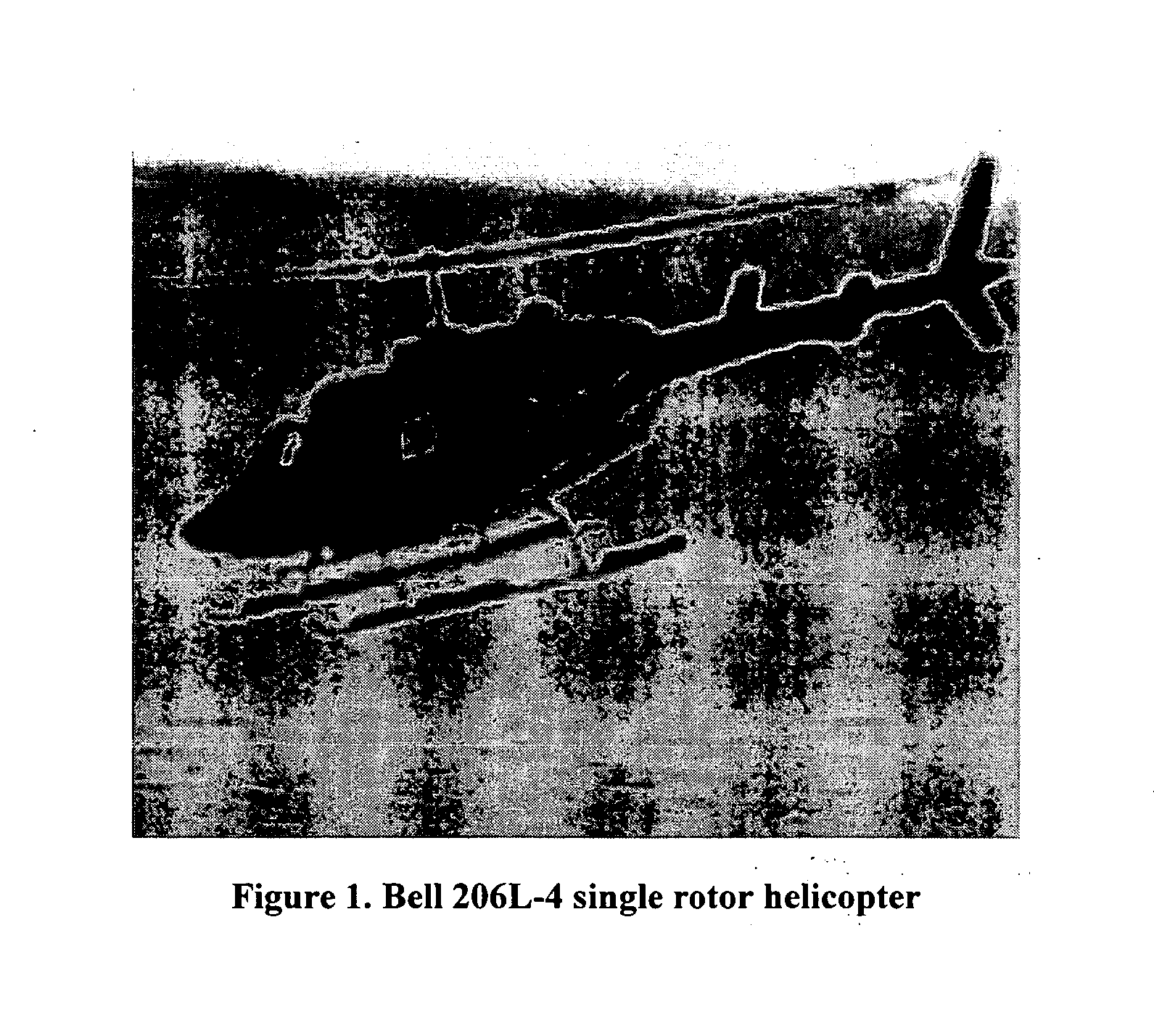
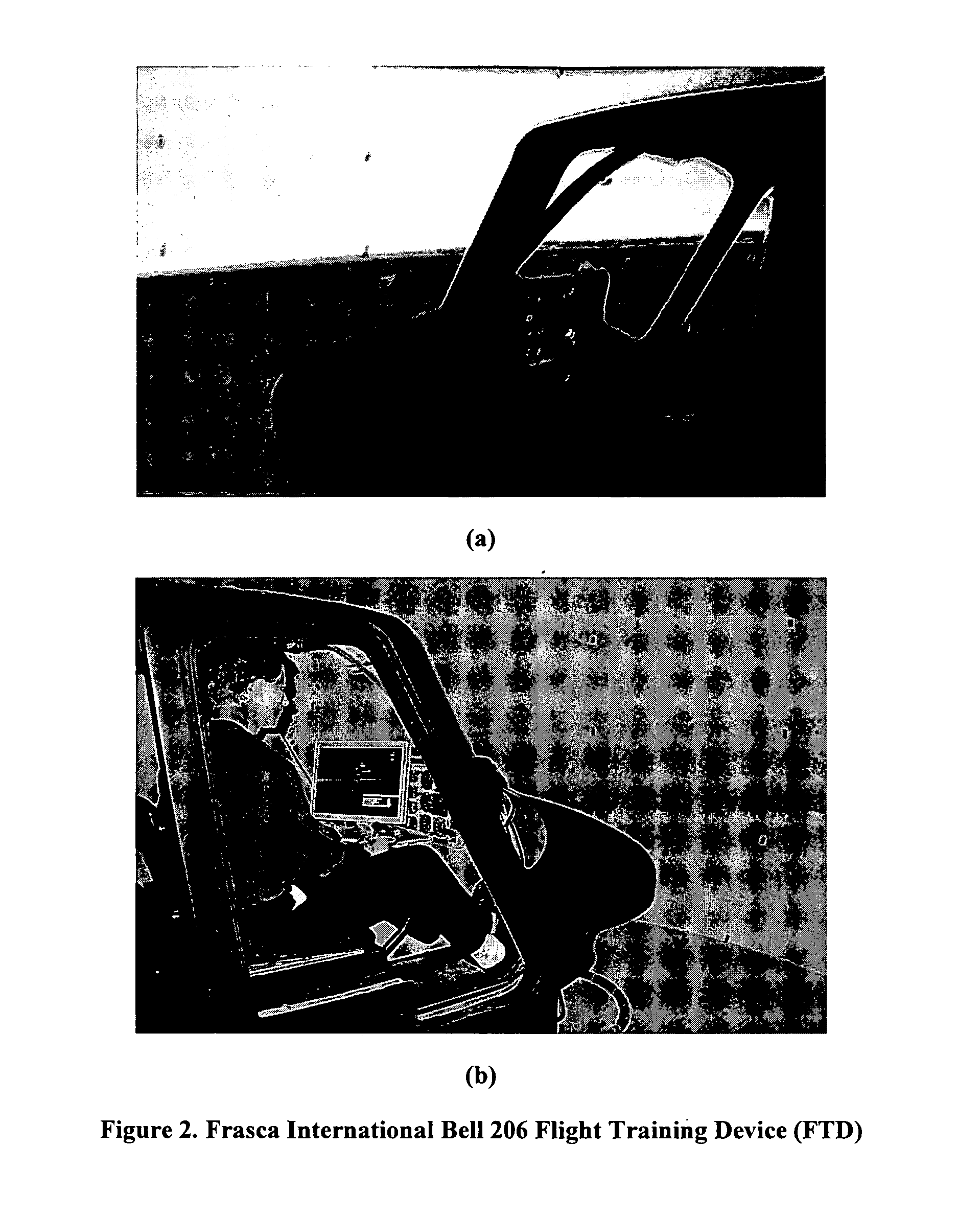
[0043] The present invention is directed to systems for autorotation flight control, and in particular to the computer implemented system that provides directions for controlling the flight of helicopters or of other rotorcraft upon loss of power to maximize the likelihood of a safe landing. The present invention may take the form of various embodiments, such as for example in a system adapted for a flight simulator for single engine, single rotor helicopters, a flight simulator for multiple engine, single or multiple rotor helicopters or a flight simulator for other rotorcraft. Embodiments of the present invention may also take the form of control systems for use in real working helicopters or other rotorcraft (as opposed to a simulator). When adapted for use in piloted working aircraft, the system is be adapted to provide display information for controlling the flight of the aircraft to maximize the likelihood of safe landing and / or is be adapted to provide automatic control input...


PUM


Abstract

The present invention provides computer implemented methodology that permits the safe landing and recovery of rotorcraft following engine failure. With this invention successful autorotations may be performed from well within the unsafe operating area of the height-velocity profile of a helicopter by employing the fast and robust real-time trajectory optimization algorithm that commands control motion through an intuitive pilot display, or directly in the case of autonomous rotorcraft. The algorithm generates optimal trajectories and control commands via the direct-collocation optimization method, solved using a nonlinear programming problem solver. The control inputs computed are collective pitch and aircraft pitch, which are easily tracked and manipulated by the pilot or converted to control actuator commands for automated operation during autorotation in the case of an autonomous rotorcraft. The formulation of the optimal control problem has been carefully tailored so the solutions resemble those of an expert pilot, accounting for the performance limitations of the rotorcraft and safety concerns.

Description

[0001] The United States Government has a paid-up license in this invention and the right in limited circumstances to require the patent owner to license others on reasonable terms as provided for by the terms of NASA Contracts NAS2-02008 and NAS2-02096 awarded by the NASA, Ames Research Center, Moffett Field, Calif.FIELD OF THE INVENTION [0002] The present invention relates to a methodology using optimal control for application to the time critical maneuvering of dynamic systems including vehicles such as rotorcraft. The methodology is implemented in a computer-based system for calculating and displaying optimal-control input commands to a human-operator for autorotation flight control of a rotorcraft and is adapted for training helicopter pilots in a flight simulator on safe maneuvering in time critical situations involving total engine power failure (autorotation) and partial power failure. The methodology can also be used for automated guidance of dynamic systems including vehic...

Claims


Application Information

Patent Timeline
IPC IPC(8): B64C13/04
CPCG05D1/102G05D1/0072G05D1/105
Inventor BACHELDER, EDWARD N.LEE, DONG-CHANAPONSO, BIMAL L.
Owner SUBARU TECNICA INTERNATIONAL
Why Eureka
Try Eureka