

Nanoparticle heating and applications thereof
a technology of nanoparticles and nanoparticles, applied in the field of magnetic nanoparticles, can solve the problems of man-made machines in terms of efficiency, precision, complexity, and control and fine-tuning of such systems, and remain a bit out of reach
- Summary
- Abstract
- Description
- Claims
- Application Information
AI Technical Summary
Problems solved by technology
Method used
Image

Examples
example 1
Power Loss As A Function of Frequency
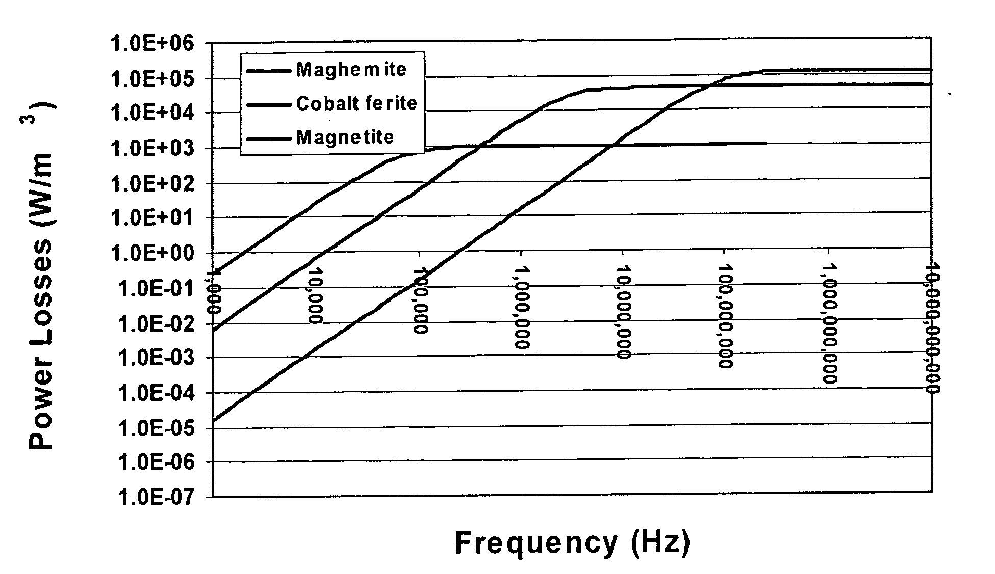
[0154] By exploiting the size and material dependence of nanoparticle heating, a method for independently heating different nanoparticle types can be achieved, since power loss (P) is a function of the material property, magnetic field frequency and particle size.
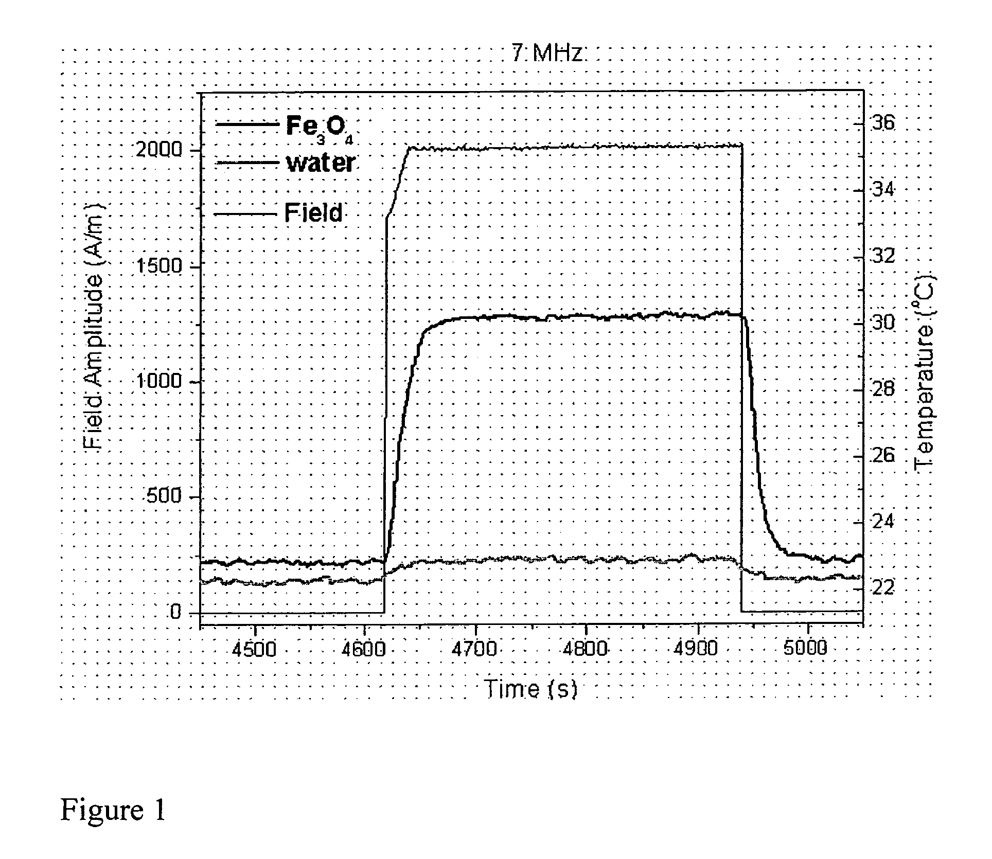
[0155]FIG. 1 demonstrates the calculated frequency dependence for Fe3O4 particles. The specific absorbance rate (SAR) is calculated according to EQ. 5: SAR?cⅆTⅆt(EQ. 5)
[0156] Where c=the specific heat capacity of the solution and dT / dt=the temperature increase per unit time.
[0157] SAR is also approximated by the following equation:
SAR ? kfn Hm (EQ. 6)
[0158] Where n=1.0-1.5 and m≈2.0.
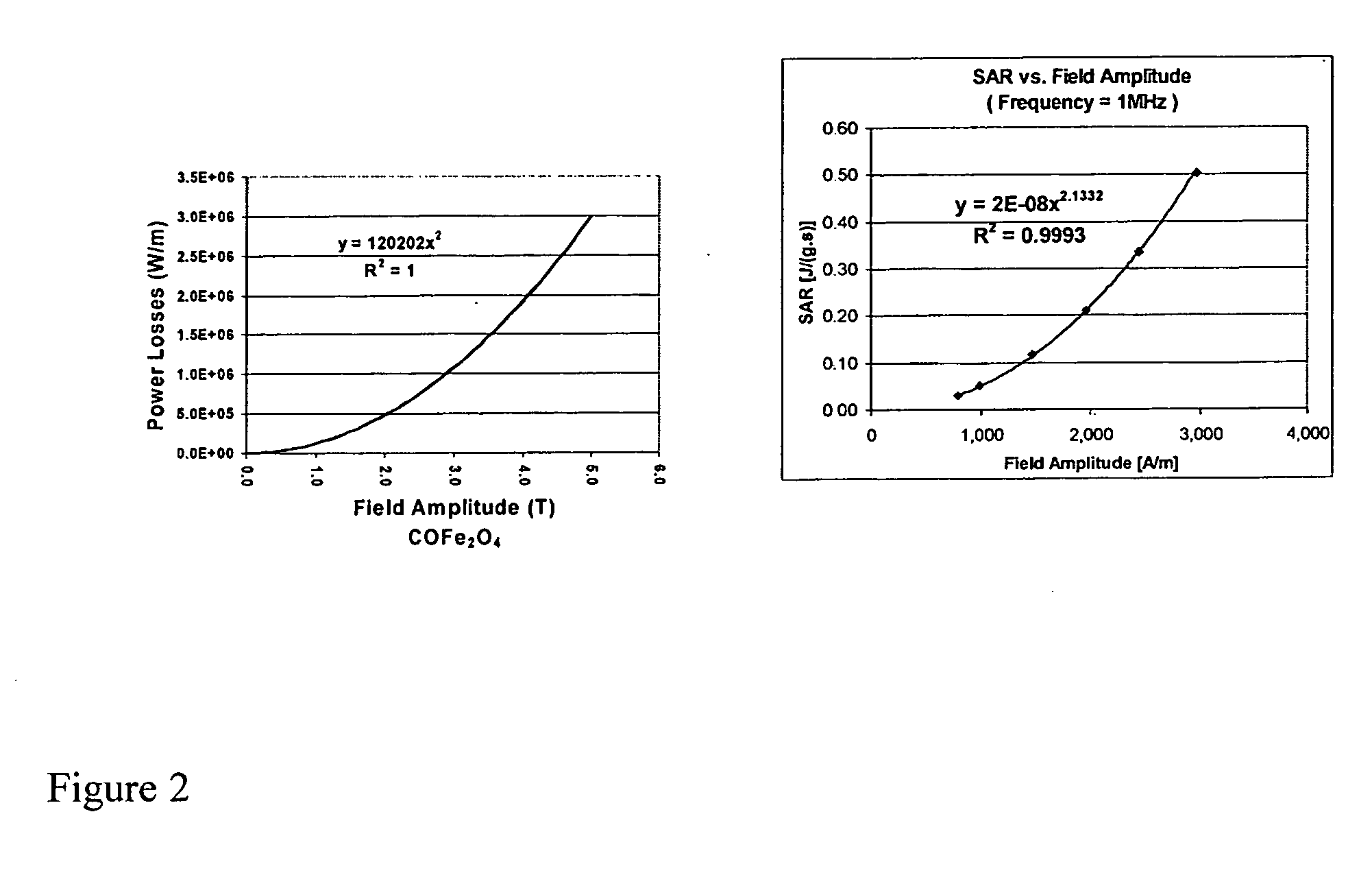
[0159]FIG. 2 demonstrates the calculated field amplitude dependence for CoFe2O4.
[0160] Thus, field amplitude, which is dependent upon the specific frequency, varies as a function of SAR or power loss.
example 2
Varied Frequency And Field Amplitude Applied To Nanoparticles of Different Materials
[0161] In one embodiment, three types of nanoparticles of different materials can be shown to have heating curves, which differ, as a function of frequency, shown in FIG. 3A. The frequency dependence is seen to vary depending upon the material of the particle used.
[0162] Nanoparticle size also plays a role (FIG. 3B), with optimal nanoparticles size for given material represented by the peak for each material. A representative SEM for some of the particles are shown in FIG. 3C.
[0163] Even greater control may be achieved, via tuning of the 3 variables (FIG. 3D). Application of a 90mT field at frequency f1 heats CoFe2O4 nanoparticles, and Fe3O4 and Fe2O3 particles are not heated to the same degree. Application of a lower field (10mT) at a frequency of f2 preferentially heats Fe3O4 particles, with CoFe2O4 nanoparticles, and Fe2O3 particles not heated to the same degree, etc. The manipulation of these ...
example 3
Nanoparticle Heating Applications
[0164] Independent heating of nanoparticles may be applied to a multitude of applications, including biomolecular applications. The nanoparticles may serve as an antenna, whereby inductive heating of the nanoparticles heats a biomolecule attached to the nanoparticles.
[0165] In some embodiments, such specifically applied heat induces a conformational change in the protein, which may convert a biologically inactive form to an active form, or vice versa (FIG. 4A). Another application is the ability to provide a localized heat force. The methods provide the ability to address multiple biomolecules independently, using size dependence, materials dependence, or a combination thereof (FIG. 4B).
[0166] Some applications of the technique include the ability to non-invasively burn tumors for cancer therapy, by application of an alternating magnetic field. Each nanoparticle type can be functionalized to incorporate targeting moieties, for example, antibodies ...
PUM
| Property | Measurement | Unit |
|---|---|---|
| Composition | aaaaa | aaaaa |
| Magnetic field | aaaaa | aaaaa |
| Structure | aaaaa | aaaaa |
Abstract
Description
Claims
Application Information