Contact lithography apparatus and method employing substrate deformation

a technology of contact lithography and substrate, applied in the field of semiconductors, can solve the problems of limiting the applicability and ultimate marketability of contact lithography, affecting the patterning of trapped gas bubbles, and affecting the patterning, so as to reduce the retention force

Inactive Publication Date: 2007-07-19
HEWLETT PACKARD DEV CO LP
View PDF68 Cites 11 Cited by
  • Summary
  • Abstract
  • Description
  • Claims
  • Application Information

AI Technical Summary

Benefits of technology

[0009] In other embodiments of the present invention, a method of transferring a pattern to a surface is provided. The method comprises establishing a proximal, spaced apart arrangement of a patterning tool and a substrate. The method of transferring further comprises deforming the substrate toward the patterning tool to form an initial point of contact between the patterning tool and the substrate. Deforming the substrate comprises reduci...

Problems solved by technology

As the patterning tool contacts the substrate, gas bubbles may be trapped at an interface between the patterning tool and the substrate.
Trapped gas bubbles adversely affect patterning by introducing defects in the transferred pattern.
The use of high contact pressure and being restricted to using gas absorbing and...

Method used


Image

  • Contact lithography apparatus and method employing substrate deformation
  • Contact lithography apparatus and method employing substrate deformation
  • Contact lithography apparatus and method employing substrate deformation

Examples


Embodiment Construction

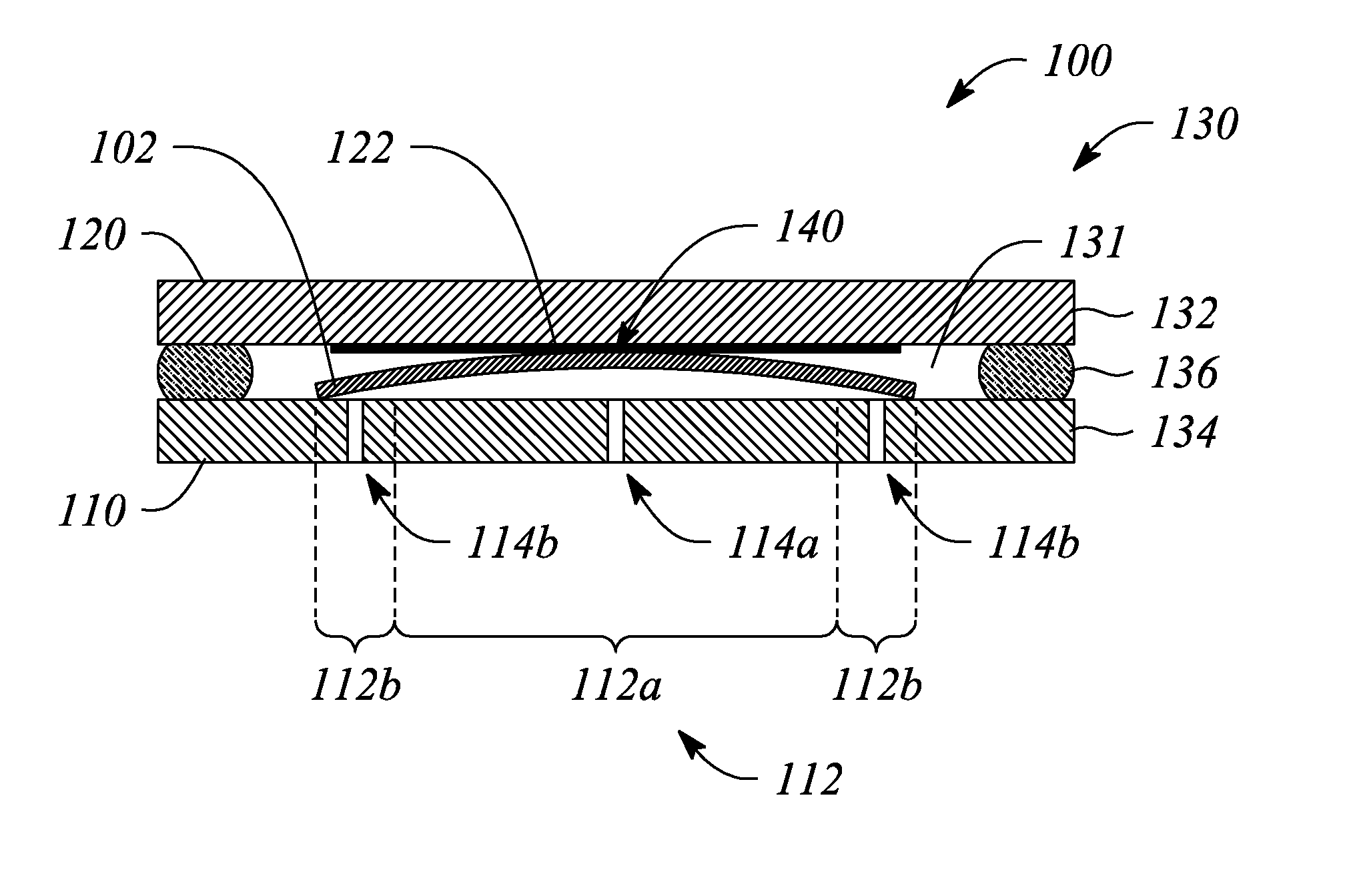
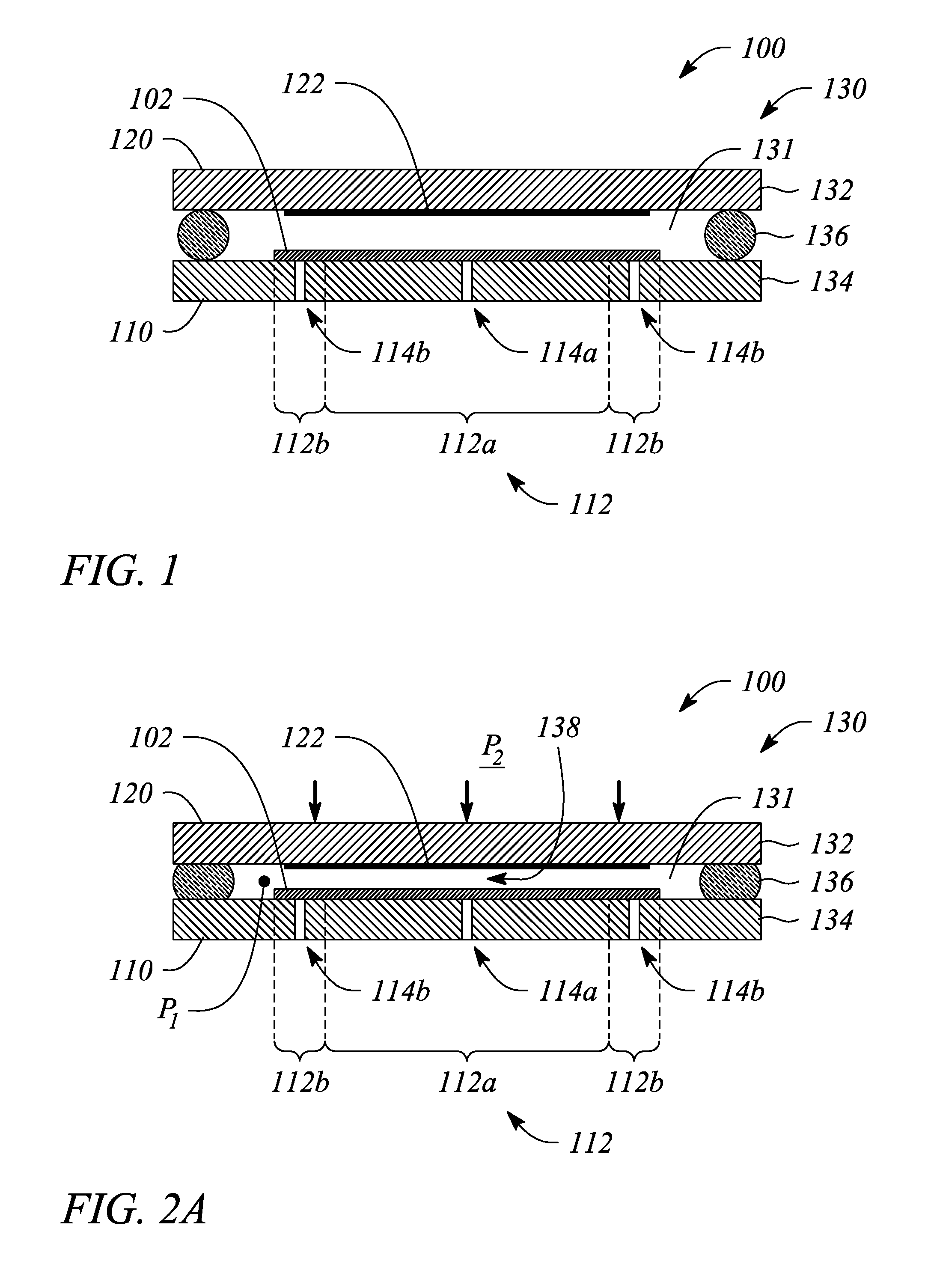
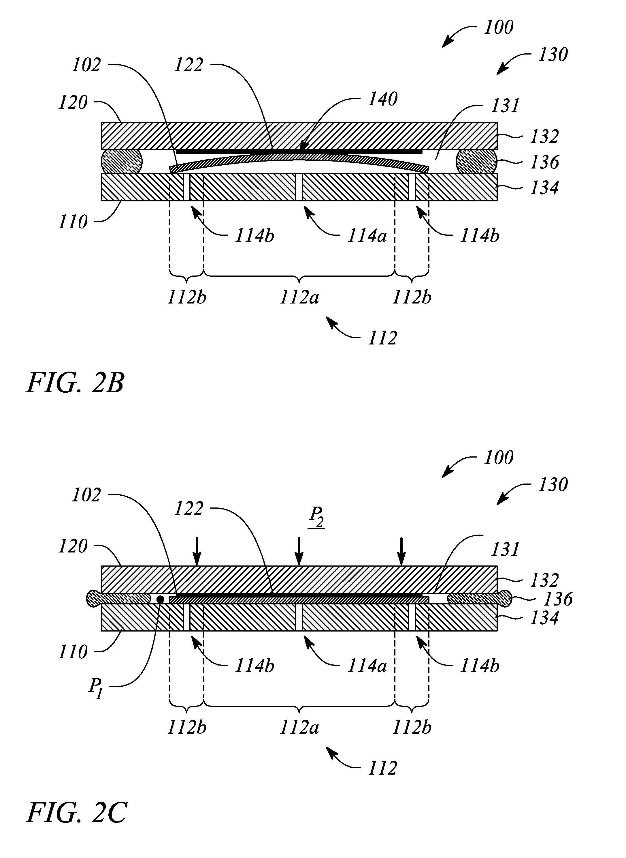
[0019] Embodiments of the present invention facilitate contact lithography wherein a pattern defined by a patterning tool is transferred to, imprinted on or pressed into a surface of a sample or substrate. In particular, a pressure applied to one or both of the patterning tool and the substrate produces a direct physical contact between the patterning tool and the substrate. The applied pressure presses at least one protruding feature of the patterning tool pattern onto or into a receiving surface of the substrate. As a result of the pressure-induced contact during contact lithography, a negative image copy of the patterning tool pattern is created on or in the receiving surface.

[0020] According to the embodiments of the present invention, application of the pressure during contact lithography establishes an initial contact point between the patterning tool and the substrate. Furthermore according to various embodiments of the present invention, the initial contact point occurs at ...


PUM

PropertyMeasurementUnit
Forceaaaaaaaaaa
Pressureaaaaaaaaaa
Deformation enthalpyaaaaaaaaaa

Abstract

A contact lithography apparatus and a method of transferring a pattern to a surface employ deformation of a substrate for pattern transfer. The contact lithography apparatus includes a patterning tool and a substrate holder that variably retains a substrate. The substrate holder includes a plurality of retention zones. Each retention zone imparts a zone-specific retention force to the substrate that induces a deformation of the substrate toward the patterning tool. The method includes deforming the substrate. The deformation forms both an initial point of contact and a propagating contact front between the patterning tool and the substrate during pattern transfer.

Description

CROSS-REFERENCE TO RELATED APPLICATIONS [0001] This application is a continuation-in-part of U.S. patent application Ser. No. 10 / 931,672, filed Sep. 1, 2004, the disclosure of which is incorporated herein by reference.BACKGROUND [0002] 1. Technical Field [0003] The invention relates to semiconductors and the fabrication thereof. In particular, the invention relates to contact lithography used to define one or both of micro-scale and nano-scale structures during semiconductor fabrication. [0004] 2. Description of Related Art [0005] Photographic contact lithography and imprint lithography are examples of two contact lithography methodologies for defining micro-scale and nano-scale structures that involve direct contact between a patterning tool (e.g., mask, mold, template, etc.) and a substrate on which the structures are to be fabricated. In particular, during photographic contact lithography, the patterning tool (i.e., mask) is aligned with and then brought in contact with the subst...

Claims


Application Information

Patent Timeline
IPC IPC(8): B29C59/02
CPCB82Y10/00G03F7/0002B82Y40/00
Inventor WU, WEITONG, WILLIAM M.
Owner HEWLETT PACKARD DEV CO LP
Why Eureka
Try Eureka