

Capacitive micromachined ultrasonic transducer
a micromachined ultrasonic transducer and capacitive technology, applied in the field of capacitive micromachined ultrasonic transducers, can solve the problem that ultrasonic waves at high frequencies are subjected to attenuation at deeper portions
- Summary
- Abstract
- Description
- Claims
- Application Information
AI Technical Summary
Problems solved by technology
Method used
Image

Examples
first embodiment
[0065] In the present embodiment, a capacitive micromachined ultrasonic transducer is explained. In this capacitive micromachined ultrasonic transducer, high-frequency waves are transmitted from the central spot, and the closer to the circumference the spot from which waves are transmitted is, the lower the frequency of the transmitted waves.
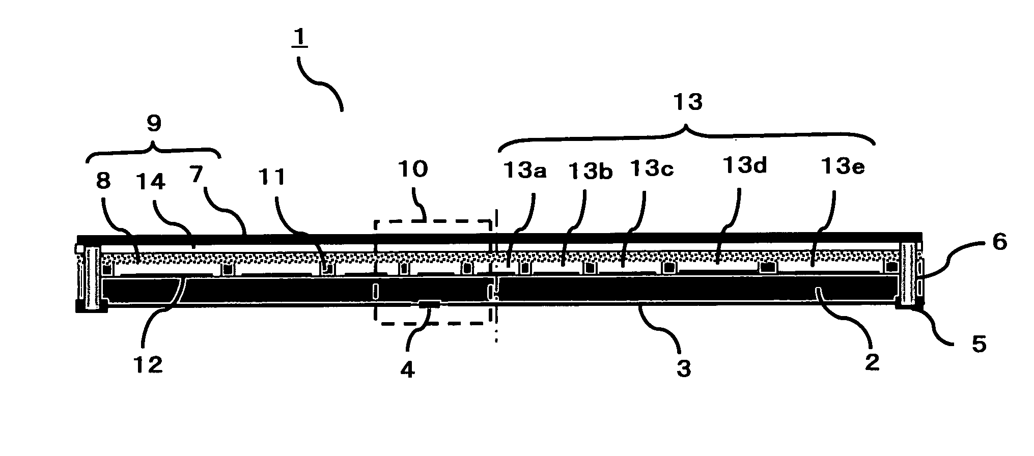
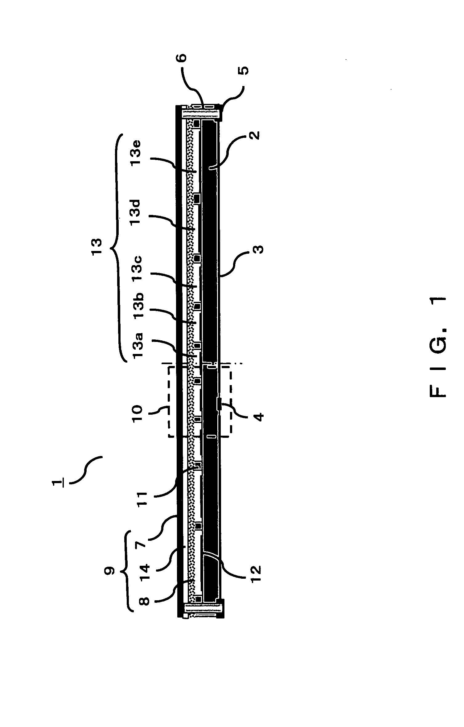
[0066]FIG. 1 shows a basic configuration of a capacitive micromachined ultrasonic transducer (c-MUT) according to the present embodiment in a cross-sectional view. The unit of the c-MUT shown in FIG. 1 is referred to as an transducer element 1 (simply referred to as an element, hereinafter) The c-MUT includes a plurality of recesses on the surface of a silicon substrate 2. This unit is referred to as an transducer cell 10 (simply referred to as a cell, hereinafter). A membrane 9 is set on the upper face of the silicon substrate 2 such that the respective cells 10 are covered.
[0067] The membrane 9 is an oscillation film whose end portions are f...
second embodiment
[0110] In the present embodiment, cells having apertures in various shapes are formed in elements, and high-frequency waves are transmitted from the central spot of the element and low-frequency waves are transmitted from the spots around the central spot.
[0111]FIG. 5A-5D shows the upper face of an element according to the present embodiment. FIG. 5A shows an element 40 in an oval shape in which a plurality of cells 41 in an oval shape are formed. The central cell has the smallest area, and the closer to the periphery of the element a cell is, the larger the area of the cell.
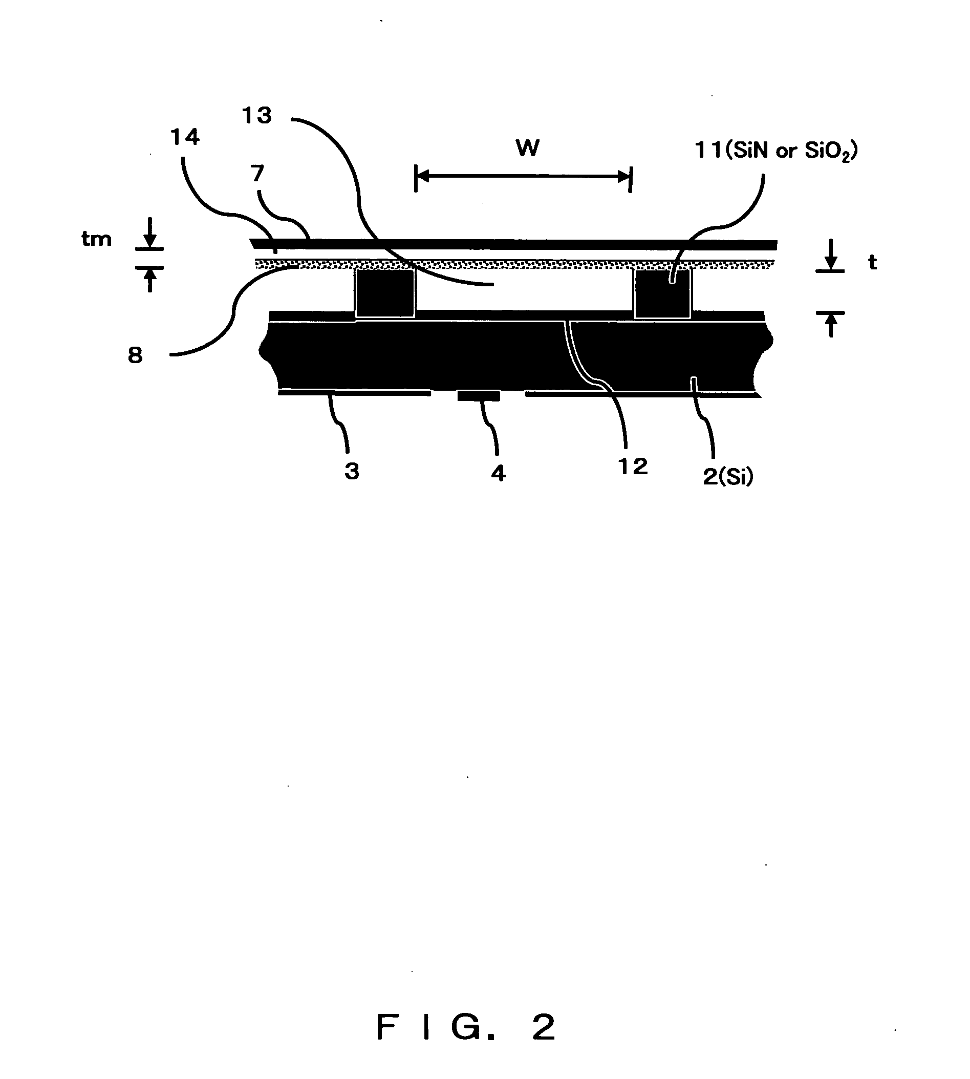
[0112] As described above, by changing the membrane width W, the frequency can be changed to being in inverse proportion to W2 (see equation (1)). Thus, when a cell having a small area at the central point of the element is formed and when other cells are arranged such that the closer to the periphery of the element a cell is, the larger the area of the cell, high-frequency waves are transmitted from the centr...
third embodiment
[0115] In the present embodiment, a capacitive micromachined ultrasonic transducer is realized in which a plurality of elements are arranged such that the central element transmits a high-frequency wave, and the further an element is from the central element, the lower the frequency of waves transmitted from the element, and in which the same effect as that of the first embodiment is achieved by an electric control without physically curving the ultrasonic wave transmission / reception surface.
[0116]FIG. 6 shows a unit of the capacitive micromachined ultrasonic transducer according to the present embodiment. On a substrate 54, a plurality of elements 51 (nine elements, 51a, 51b, 51c, 51d, 51e, 51d, 51c, 51b, and 51a) are arranged. In this embodiment, this group of elements 51 is referred to as a unit 50.
[0117]FIG. 7 shows the upper face of the element 51 according to the present embodiment. In the element 51, sixteen (four×four) cells 60 are arranged in a square shape. Because these...
PUM
 Abstract
Description
Claims
Application Information