
System and method for locking electronic devices

a technology of electronic devices and locking systems, applied in the field of electronic device security, can solve problems such as unsatisfactory solutions, interruptions, and other electronic devices that could pose security risks if left unattended, and achieve the effect of adding to the security of a user's computer and other electronic devices

Inactive Publication Date: 2007-07-19
IBM CORP
View PDF13 Cites 46 Cited by
  • Summary
  • Abstract
  • Description
  • Claims
  • Application Information

AI Technical Summary

Benefits of technology

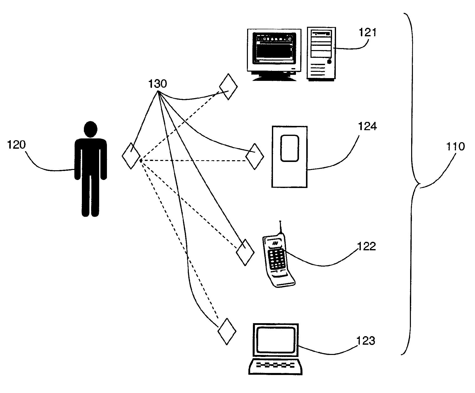
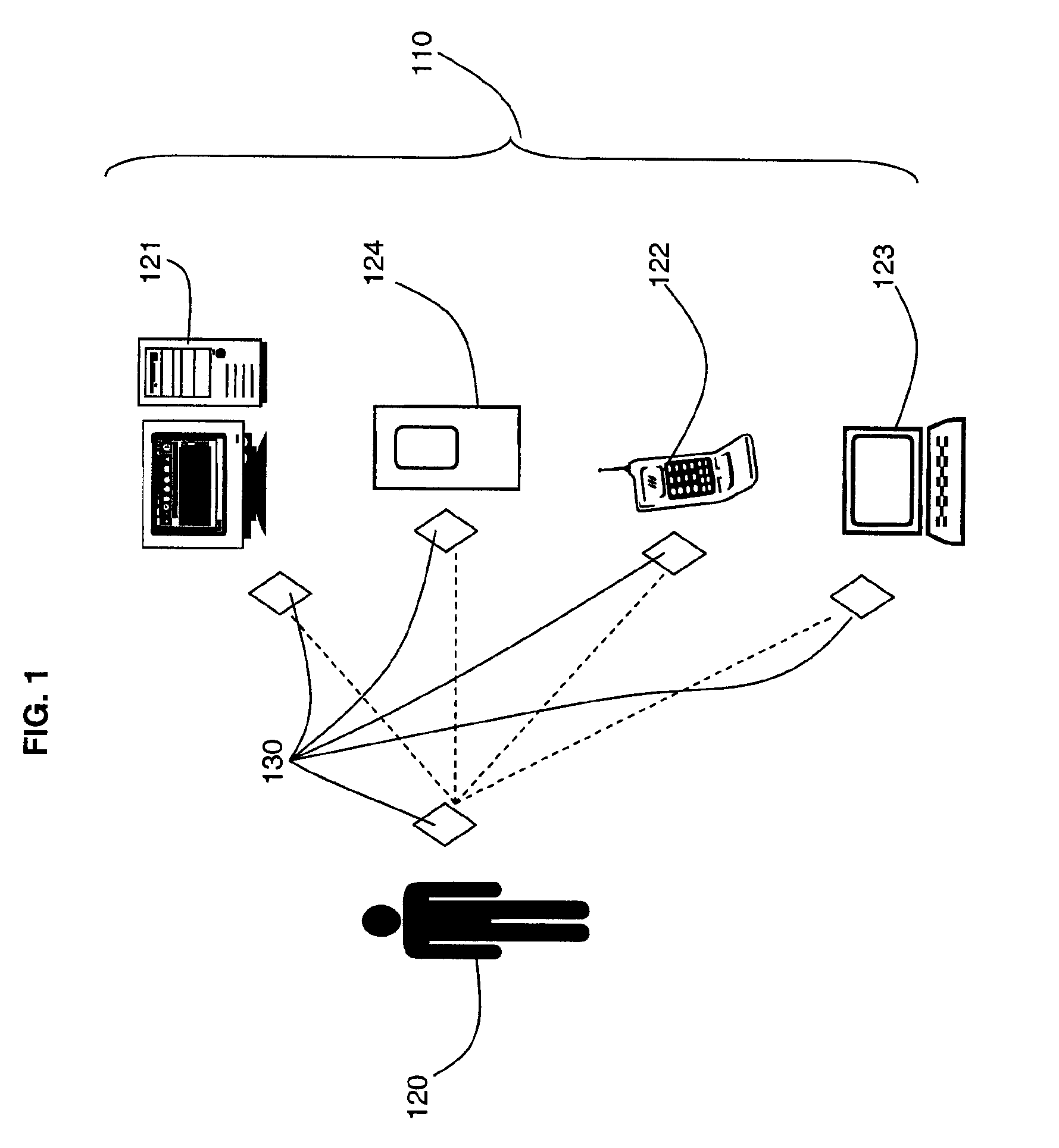
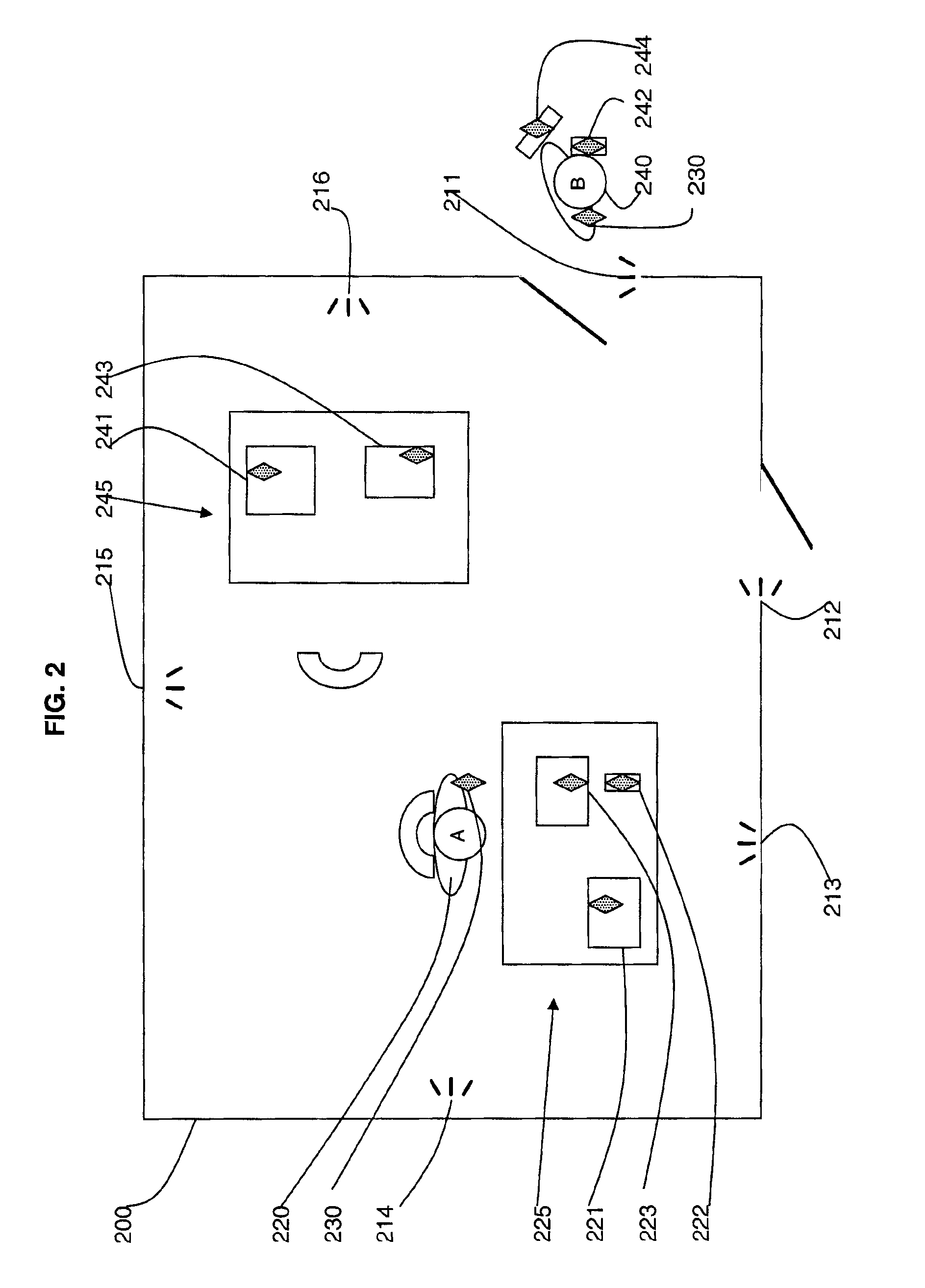
[0018]The core idea of this invention involves attaching identification tags to computers and their operators. Each office space has tag sensors at the entrances that have the ability to track movement of tags through them. In this way, it is possible to determine the location of an employee and the employee's associated electronic devices. On detecting an employee leaving the office, the system will ascertain the location of the employee's electronic devices. If an electronic device associated with the employee is in a different location to the employee, a lock command is sent to the electronic device.
[0019]This solution adds to the security of a user's computer and other electronic devices, and readily complements the current solution of locking a computer after a period of inactivity.

Problems solved by technology

Similarly, other electronic devices that could pose a security risk if left unattended, must also be secured.
However, this solution is not ideal.
A disadvantage of this apparatus is that the device is attached to the computer and therefore, each computer must have its own device.
Another disadvantage is that as the device replicates keystrokes with a time lapse, they are subject to interruption by someone using the keyboard itself.

Method used


Image

  • System and method for locking electronic devices
  • System and method for locking electronic devices
  • System and method for locking electronic devices

Examples


Embodiment Construction

[0026]A security system is provided in which one or more users and a plurality of devices are tagged with electronic tags and the system activates locking commands on the devices when they are not in the same location as their designated user.

[0027]An embodiment of such electronic tags is provided by Radio Frequency Identification (RFID) technology, although other forms of tags and readers may be used.

[0028]Radio frequency identification (RFID) technology exists in which tags are provided in the form of transponders that are embedded in items to act as identifiers of the items. Readers or scanners act as an interface between the transponders and a data environment. Transponders and the means used to read them are available is a number of forms. Any suitable form can be used for the purposes of the present invention.

[0029]The antenna emits radio signals to activate the tag and to read and / or write data to it. Antennas can be built into a door frame to receive tag data from persons or...


PUM


Abstract

A system and method are provided for locking electronic devices when the devices are not in the same location as a user associated with the device. The system includes a plurality of users each having an identification tag and a plurality of electronic devices each having an identification tag. Location sensors are provided in a room and at entry and exit points for detecting the location of the tags. A database stores the location information of tags and associations of a user with one or more devices. A remote locking means invokes a lock command or an unlock command on an electronic device depending on whether or not the electronic device is in the same location as a user associated with the device. In one embodiment, the identification tags are radio frequency identification transponders and the location sensors are radio frequency identification readers.

Description

CROSS REFERENCE TO RELATED APPLICATIONS[0001]The present application claims priority under 35 USC 119 to United Kingdom Application Number GB0600465.9, filed Jan. 11, 2006.FIELD OF THE INVENTION[0002]This invention relates to the field of security of electronic devices and, in particular, to locking devices to prevent use by unauthorized persons.BACKGROUND OF THE INVENTION[0003]The security of information is of crucial importance within the Information Technology (IT) industry. It is as important to protect information within the constraints of an office as it is from external attacks. Taking this into account, many organizations enforce a policy where employees must lock their workstation whenever they are not at their desk. Similarly, other electronic devices that could pose a security risk if left unattended, must also be secured. Examples of these devices include telephones, laptops, and personal digital assistants (PDAs).[0004]In most modern operating systems, a user can set a ...

Claims


Application Information

Patent Timeline
Patent Type & Authority Applications(United States)
IPC IPC(8): G05B19/00
CPCG06F21/35G06F21/88H04M2250/12H04M1/7253H04M1/67H04M1/72412
Inventor CRAWFORD, MICHAELFAIRMICHAEL, FINTANO'RIORDAN, KEVIN TADGHTAPLEY, STEPHEN
Owner IBM CORP
Learn More