Radio communication system, radio communication apparatus, radio communication method, and computer program

Active Publication Date: 2007-07-19
SONY CORP
View PDF8 Cites 133 Cited by
  • Summary
  • Abstract
  • Description
  • Claims
  • Application Information

AI Technical Summary

Benefits of technology

[0107] According to the present invention, a superior wireless communication system, wireless communication device, wireless communication method, and computer program, wherein a network is formed by communication stations operating in an autonomous distributed manner without a device serving as a control station being disposed, can be provided.
[0108] Also, according to the present invention, a superior wireless communication system, wireless communication device, wireless communication method, and computer program, wherein data transmission can be performed while avoiding collision in an autonomous distributed wireless network without involvement of a specified control station, can be provided.
[0109] Also, according to the present invention, a superior wireless communication system, wireless communication device, wireless communication method, and computer program, wherein beacon collision can be appropriately avoided among multiple communication stations in a network configured by communication stations performing notification with beacons can be

Problems solved by technology

However, there is the problem with a wireless communication system which has an access point in that asynchronous communication between transmitting and receiving communication devices always necessitates wireless communication via the access point, meaning that the usage efficiency of the transmission path is halved.
It is know that with wireless LAN networks under an ad-hoc environment, a hidden terminal problem generally occurs.
A hidden terminal is a terminal which can be heard from one communication station which is the other part of communication therewith in a case of communication

Method used


Image

  • Radio communication system, radio communication apparatus, radio communication method, and computer program
  • Radio communication system, radio communication apparatus, radio communication method, and computer program
  • Radio communication system, radio communication apparatus, radio communication method, and computer program

Examples


Embodiment Construction

[0116] Embodiments of the present invention will now be described in detail with reference to the drawings.

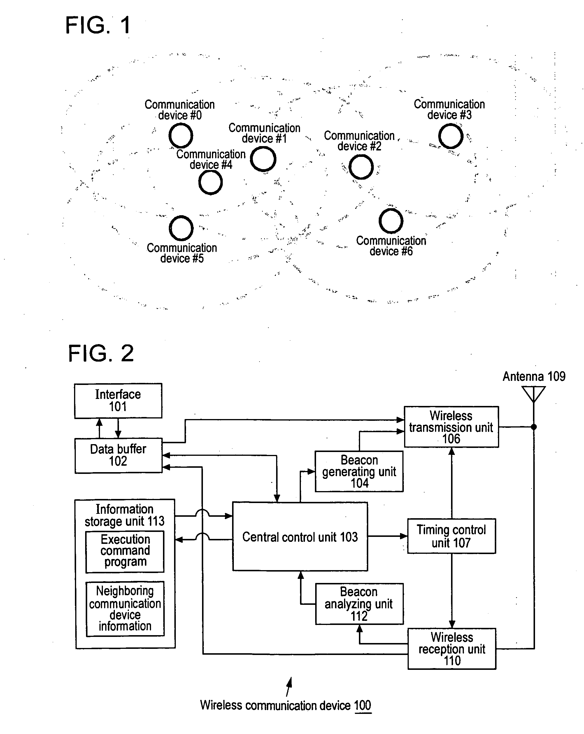
A. System Configuration

[0117] The communication transmission path serving as the basis for the present invention is wireless, with multiple communication stations configuring a network. The communication serving as the basis for the present invention is storage exchange type traffic, with information being transferred in increments of packets. Also, while the following description assumes that each communication station handles a single channel, this can be expanded to an arrangement wherein multiple frequency channels are used, i.e. multi-channel transmission media is used.

[0118] The wireless network system according to the present invention is an autonomously dispersed system configuration wherein a coordinator is not provided, and transmission control effectively using channel resources by transmission (MAC) frames having a loose time-division multiple-access structure i...


PUM


Abstract

An autonomously dispersed type wireless network is suitably formed with communication stations avoiding collision of beacons transmitted one to another. In the event that the range of reach of airwaves change and a receivable state is created and beacons collide, a communication station changes the beacon transmission position of itself in response to receiving a beacon from another station at a timing immediately prior to transmission to its own beacon. Also, in the event that beacon collision is exposed due to emergence of a new communication which can perform reception from two systems out of airwave range of each other, the newly-participating station requests one of the communication stations of which the beacons are colliding to change the beacon transmission timing.

Description

TECHNICAL FIELD [0001] The present invention relates to a wireless communication system, a wireless communication device, a wireless communication method, and a computer program, for performing mutual communication between multiple wireless stations such as with a wireless LAN (Local Area Network), and more particularly relates to a wireless communication system, a wireless communication device, a wireless communication method, and a computer program, wherein a wireless network is structured by the communication stations operating in an autonomous distributed manner without any controlling-station / controlled-station relations. [0002] More specifically, the present invention relates to a wireless communication system, a wireless communication device, a wireless communication method, and a computer program, wherein an autonomous distributed wireless network is formed by the communication stations notifying one another at predetermined frame cycles with beacons describing network infor...

Claims


Application Information

Patent Timeline
IPC IPC(8): H04J3/00H04Q7/00H04L12/44H04L12/28H04W16/14H04W48/08H04W48/10H04W56/00H04W72/12H04W84/18
CPCH04W16/14H04W72/0446H04W72/1242H04W48/08H04W72/569H04W74/085H04W74/0816
Inventor SAKODA, KAZUYUKI
Owner SONY CORP
Why Eureka
Try Eureka