
Developing apparatus and image forming apparatus using same

a technology of developing apparatus and image forming apparatus, which is applied in the direction of electrographic process apparatus, instruments, optics, etc., can solve the problems of poor adsorption, poor toner scattering, and insufficient use of charge-deficient toner, so as to suppress the scattering of toner and suppress the contamination of the interior

Active Publication Date: 2007-07-19
RICOH KK
View PDF30 Cites 48 Cited by
  • Summary
  • Abstract
  • Description
  • Claims
  • Application Information

AI Technical Summary

Benefits of technology

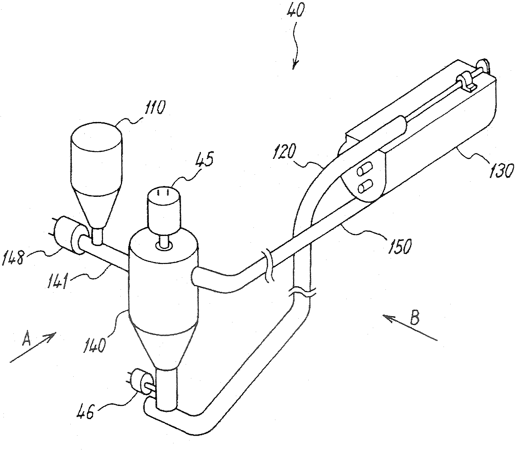
[0014] The present invention has been designed in consideration of the problems described above, and a first object thereof is to provide a developing apparatus capable of suppressing toner scattering that may occur when a development operation is halted for a long time, thereby suppressing contamination of the interior of the apparatus, and an image forming apparatus comprising the developing apparatus.
[0015] A second object of the present invention is to provide a developing apparatus capable of suppressing toner scattering after a stirring unit is replenished with a large amount of toner, thereby suppressing contamination of the interior of the apparatus, and an image forming apparatus comprising the developing apparatus.
[0016] A third object of the present invention is to provide a developing apparatus capable of extending the life of a developer in a developing method using a two-component developer, and an image forming apparatus comprising the developing apparatus.

Problems solved by technology

If mixing is not performed sufficiently up to the point at which the replenishment toner is supplied to the developing sleeve, charge-deficient toner that has not been charged sufficiently is used for development.
When charge-deficient toner is used for development, the charge-deficient toner contained in the developer carried on the developing sleeve scatters, leading to toner scattering.
The reason for this is that the charge-deficient toner that has not been sufficiently charged has poor adsorbability relative to the magnetic carrier, and therefore separates from the magnetic carrier and scatters easily.
As a result, the charge-deficient toner may fly up inside the developing apparatus and leak out through gaps in the developing apparatus on the periphery of the developing sleeve.
When toner scattering occurs, the interior of the apparatus is contaminated as toner adheres to other members on the periphery of the developing apparatus.
Toner scattering also occurs when toner other than the replenishment toner is charge-deficient, and this toner scattering also contaminates the interior of the apparatus.
Similarly to charge-deficient toner, uncharged toner separates from the magnetic carrier easily, and therefore, when the development operation is resumed with uncharged toner present in the developing unit, toner scattering occurs in a similar manner to the charge-deficient toner described above, contaminating the interior of the apparatus.
Even when the developer is not carried to the developer carrier, the uncharged toner in the developing apparatus flies up when the developer containing the uncharged toner is conveyed or the developing apparatus receives an external impact, and as a result, the uncharged toner leaks out through gaps in the developing apparatus and scatters.
When two-component developer containing charge-deficient toner is conveyed to the developing unit, toner scattering occurs, contaminating the interior of the apparatus.
As a result, the following problems arise.
When the developer is rubbed with a high degree of stress, the developer deteriorates, reducing the life of the developer.

Method used


Image

  • Developing apparatus and image forming apparatus using same
  • Developing apparatus and image forming apparatus using same
  • Developing apparatus and image forming apparatus using same

Examples


first embodiment

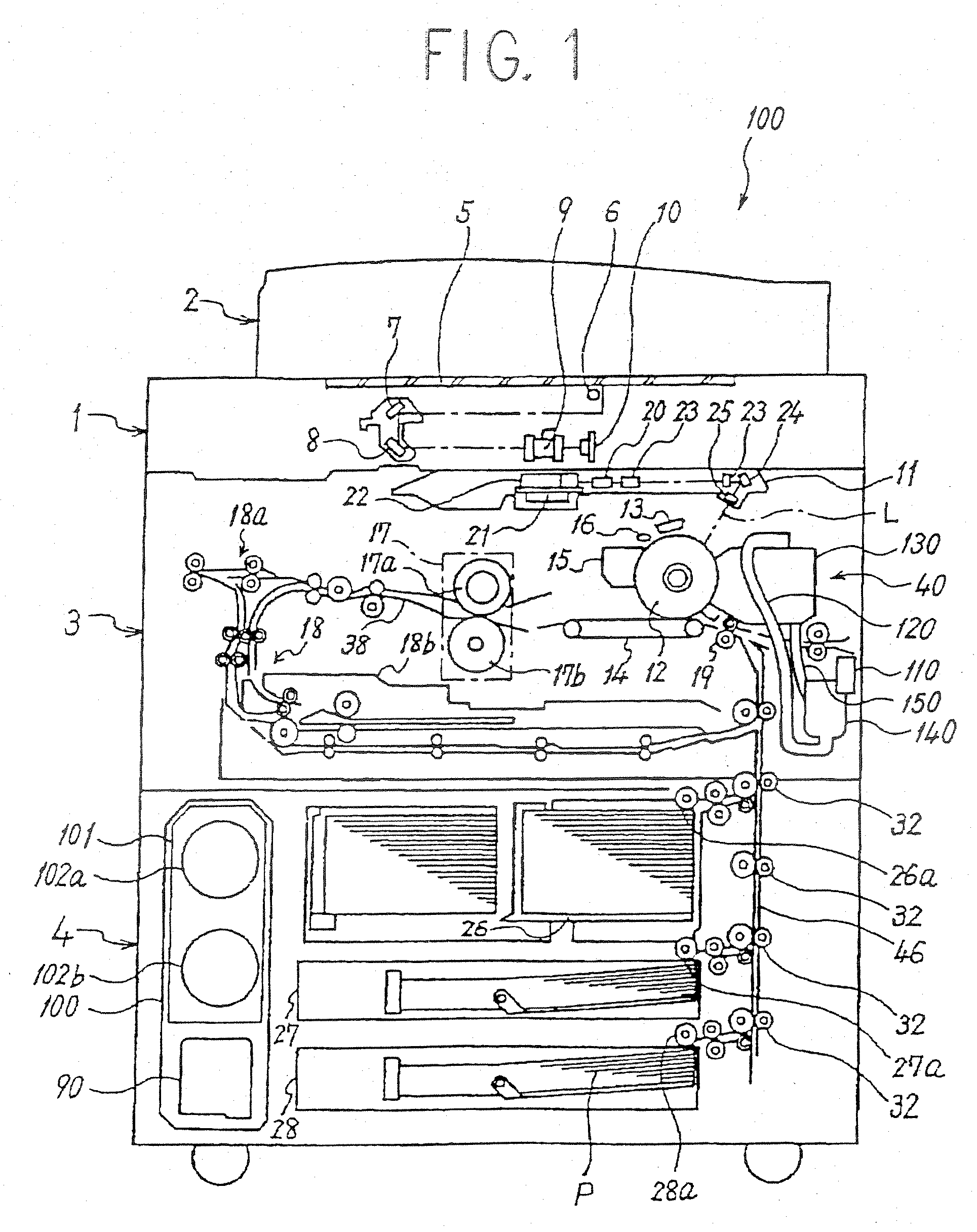
[0053] This embodiment, in which the present invention is applied to an electrophotographic system copier (to be referred to simply as a copier 100 hereafter) serving as an image forming apparatus, will now be described.

[0054] First, the basic constitution of the copier 100 according to the first embodiment will be described. FIG. 1 is a view showing the schematic constitution of the main parts of the copier 100. The copier 100 comprises an original reading unit 1, an original automatic supply unit 2, a printer unit 3, and a sheet feeding unit 4.

[0055] The original automatic supply unit 2 supplies an original, not shown in the drawing, carried on an upper surface thereof to a contact glass 5, to be described below, automatically.

[0056] The original reading unit 1 reads an image on the original, not shown in the drawing. When the original is placed on the contact glass 5 fixed to the upper portion of the original reading unit 1 through a manual user operation, and a start switch, ...

second embodiment

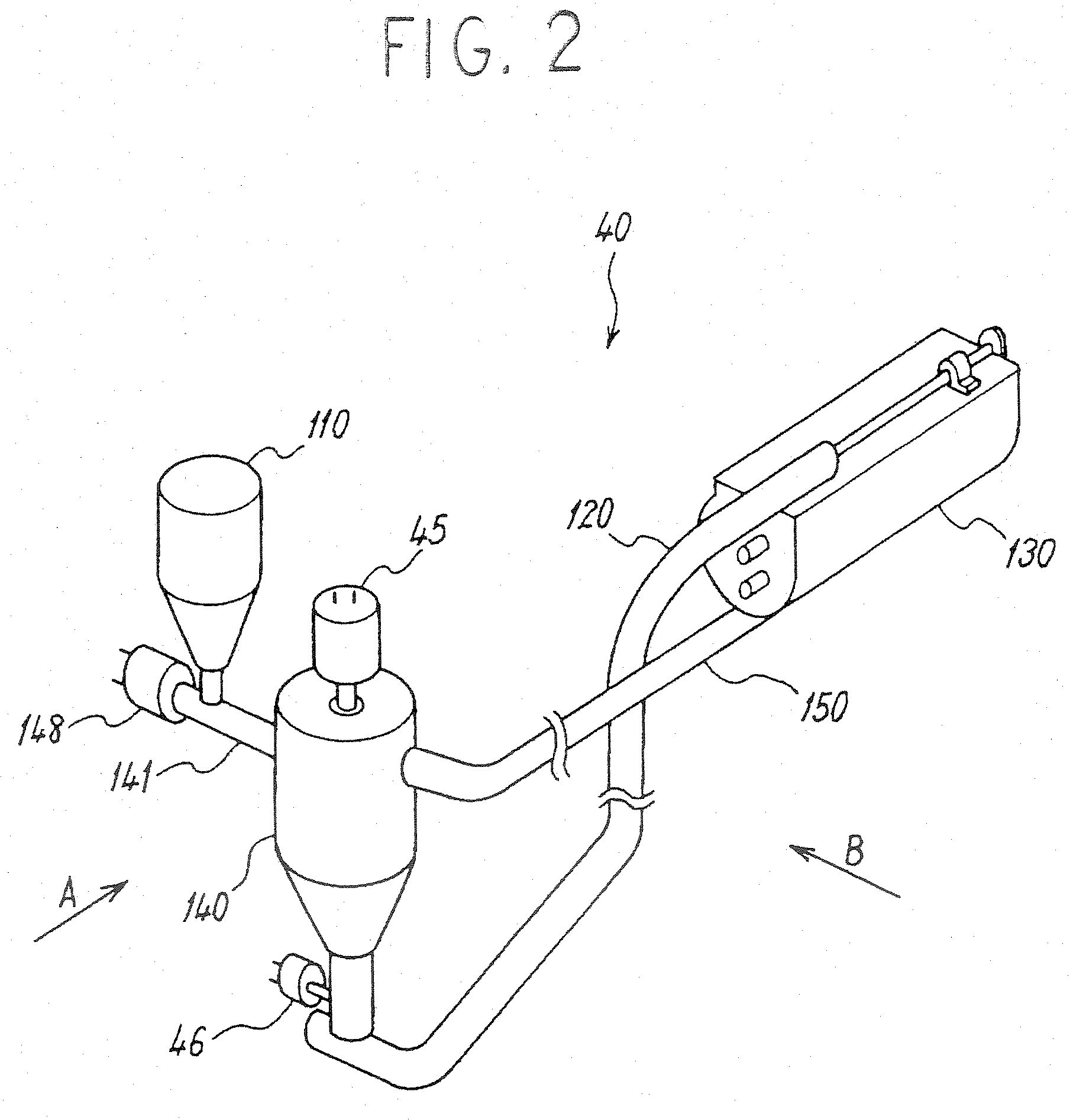
[0122] In the first embodiment described above, the developing apparatus 40, in which the developing unit and stirring unit are provided separately, was described. However, a developing apparatus in which the developing unit and stirring unit are provided integrally may be employed as a developing apparatus for preventing toner scattering caused by charge-deficient toner. Below, a developing apparatus in which the developing unit and stirring unit are provided integrally will be described as the second embodiment.

[0123]FIGS. 8A and 8B are views showing the schematic constitution of the developing apparatus 40 according to the second embodiment. FIG. 8A is a view illustrating a normal development operation, and FIG. 8B is a view illustrating a non-development period.

[0124] This developing apparatus 40 is constituted by a supply collection conveyance passage 235 serving as a developing unit for supplying developer to the developing roller 131 and collecting the developer from the de...

third embodiment

[0141] Next, a third embodiment will be described. Note, however, that FIGS. 1 to 5 and the description of the first embodiment referencing these drawings are all substantially applied to this embodiment, and therefore redundant description has been omitted, and only features of the third embodiment that differ from the first embodiment will be described.

[0142] First, the developer of the third embodiment is a two-component developer constituted by a toner having a particle diameter between 4 and 10 [μm] (volume average particle diameter), and a carrier having a particle diameter between 15 and 60 [μm] (average particle diameter, microtrack). The toner concentration depends on the size selection, but a concentration of approximately 3.5 to 10[%] is usable. The developing apparatus 40 uses a developer having a toner particle diameter of 7 [μm], a carrier particle diameter of 35 [μm] and a toner concentration of 7[%].

[0143]FIG. 9 shows the schematic constitution of the developing ma...


PUM


Abstract

A developing apparatus using a two-component developer constituted by a magnetic carrier and a toner, and an image forming apparatus comprising the developing apparatus. A developing unit and a stirring unit are provided, and in order to suppress toner scattering that may occur after a development operation has been halted for a long time, and thereby suppress contamination of the apparatus interior, the developer in a developing machine is transferred to a stirrer serving as a developer storage unit on the exterior of the developing machine when the development operation ends. Further, to extend the life of the developer, a range in which an angle of a restricting member upstream side central angle α, which is a central angle of the surface of a developing roller serving as a developer carrier on the upstream side of a restricting member opposing position opposing a doctor blade serving as a developer amount restricting member in a surface motion direction of the developing roller, is not less than 0[°] and not more than 60[°] is set as a low magnetic flux density area γ in which the maximum value of a normal direction magnetic flux density on the surface of the developing roller is not more than 30 [mT].

Description

BACKGROUND OF THE INVENTION [0001] 1. Field of the Invention [0002] The present invention relates to a developing apparatus using a two-component developer constituted by a toner and a carrier, and an image forming apparatus such as a copier, facsimile, or printer, which uses the developing apparatus. [0003] 2. Description of the Background Art [0004] A conventional developing apparatus uses a developing method in which a developer is conveyed by a developer carrier, a voltage is applied between an image carrier carrying an electrostatic latent image and the developer carrier, and toner is moved onto the electrostatic latent image to reveal the electrostatic latent image. An example of this developing method is a magnetic brush developing method using a two-component developer. In this developing method, a two-component developer constituted by a non-magnetic toner and a magnetic carrier is used, and a magnetic brush is formed by the magnetic carrier on the surface of a developing s...

Claims


Application Information

Patent Timeline
Patent Type & Authority Applications(United States)
IPC IPC(8): G03G15/08
CPCG03G21/105
Inventor ICHIKAWA, TOMOYUKIMATSUMOTO, JUNICHIIWATA, NOBUOKATOH, NATSUMI
Owner RICOH KK
Learn More