Method and apparatus for determining operational condition of pollution monitoring equipment

Active Publication Date: 2007-07-19
VFS TECH +1
View PDF4 Cites 34 Cited by
  • Summary
  • Abstract
  • Description
  • Claims
  • Application Information

AI Technical Summary

Benefits of technology

[0048] In one embodiment the extension used to access the sampling inlet from the ground level may be of an extensible tel

Problems solved by technology

While the fire itself will cause damage, considerable property damage and also environmental damage may also be caused by operation of the fire suppression system and subsequent removal of the suppressant may be quite hazardous.
A difficulty arises in operation of aspirated particle detector systems of the above kind in that as the detector is remote from the sampling point, and the detector effectively detects particles from a number of sampling points simultaneously, it is difficult to ascertain whether any particular sample point is effectively sampling particles from the environment to be protected thus enabling the detection system to be capable of detecting particles.
Furthermore, in some circumstances, one or more sampling points may block or be in a state of becoming blocked.
Smoke detectors, w

Method used


Image

  • Method and apparatus for determining operational condition of pollution monitoring equipment
  • Method and apparatus for determining operational condition of pollution monitoring equipment
  • Method and apparatus for determining operational condition of pollution monitoring equipment

Examples


second embodiment

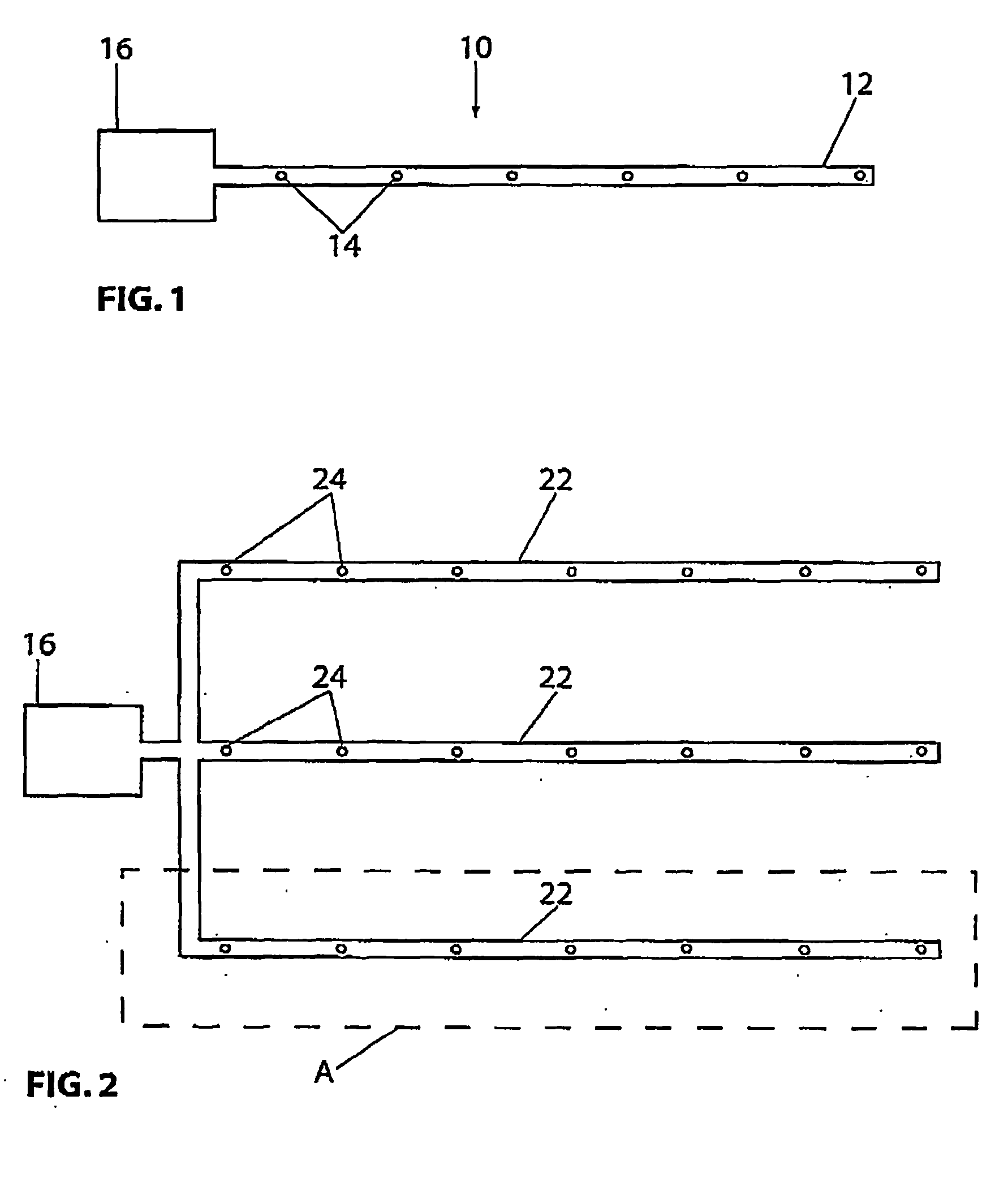
[0085] a particle detection system is shown in FIG. 2, where a pipe network 20 comprising a number of pipes 22 with sampling points 24 is shown. A similar detector to the detector 16 shown in FIG. 1 may be used. One pipe 22 may consist of a branch, such as branch A in FIG. 2.

[0086] In the above systems, air is drawn through sample points 14, 24 and into the pipe 12, 22. The pipe 12 (or 24), will have a number of sampling points 14, (or 24), and therefore air will be drawn through all sampling points within a single pipe when the sampling points are open. Typically during installation all holes are open. If all sampling points are of equal resistance to flow, there are no flow losses along the pipe, and the ambient pressure outside each sample point 14 is the same, then the airflow through all sampling points along pipe 12 will be equal. This results in equal dilution of air from each region to be sampled. Thus, for example, if there are 10 sample inlets, holes 24, and an alarm is to...

first embodiment

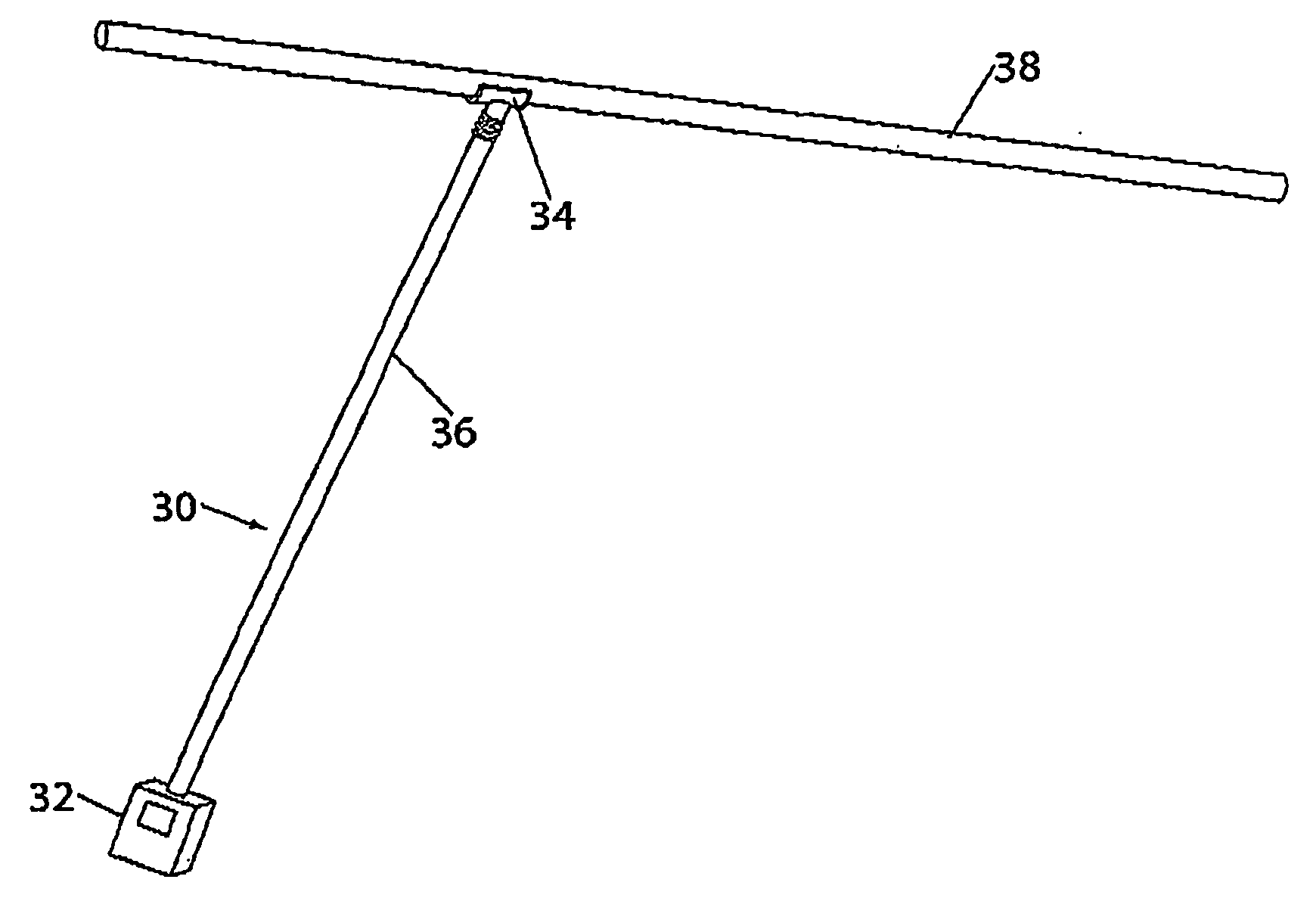
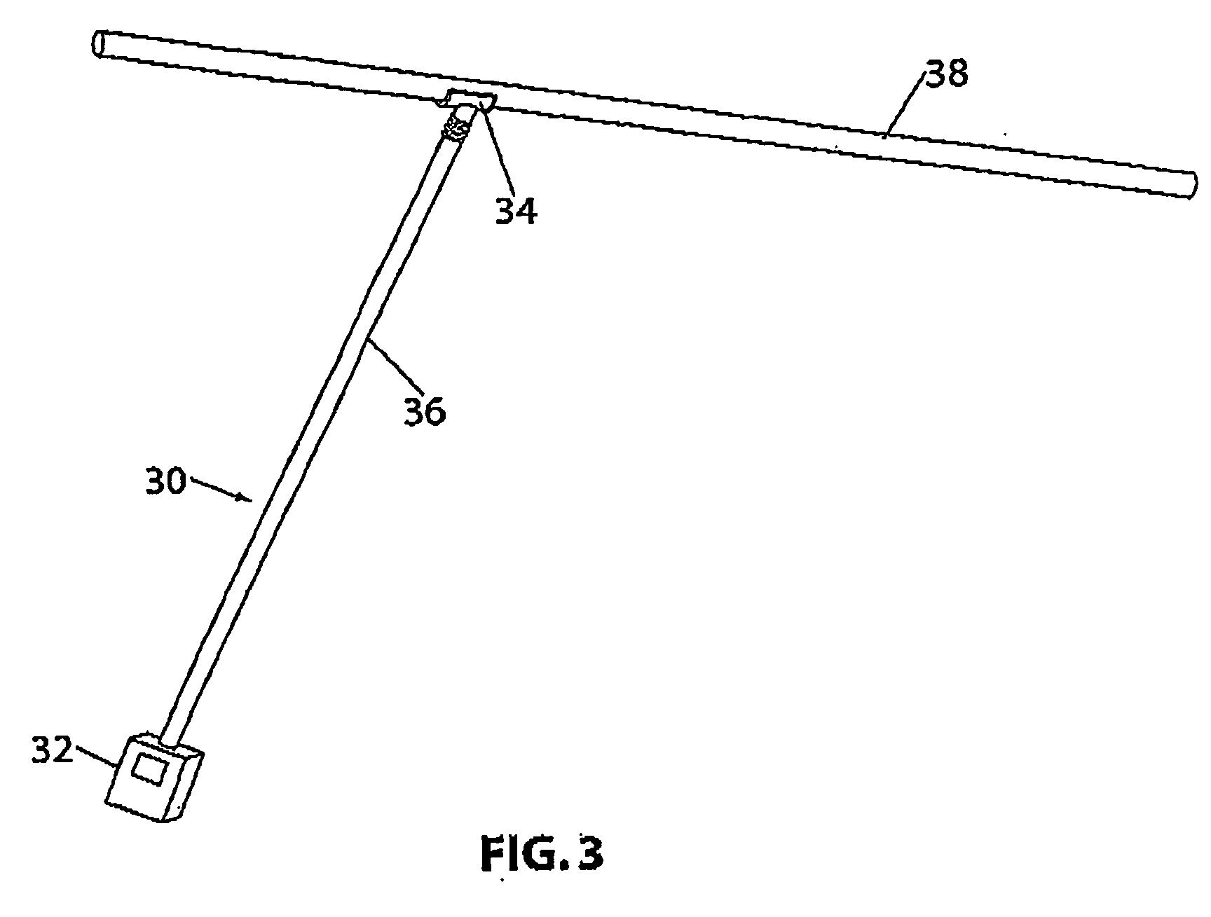
[0095] In FIG. 3 an air sampling particle detector system testing apparatus 30 is shown. Test apparatus 30 comprises a sensing device 32, which itself comprises a flow sensor, a connector 34 and an extension means 36. The connector 34 is adapted to fit over a sampling pipe 38 at a sample point (best shown in FIGS. 4, 5a, 5b and 6). The connector 34 may take a number of forms depending on the type of sampling point used in the aspirated system. Some forms of sampling point are shown in FIGS. 4, 5a, 5b and 6, but the apparatus may be used with a variety of sampling point configurations. The main feature of a connector 34 is that it is adapted to fit a sampling point in a way that provides a reasonable seal. Perfect sealing, while desirable is not required, given the relatively low pressure differentials anticipated in measuring air flow through the sampling points. Sampling points typically have holes from about 2 mm and larger in diameter. Hole 37 represents one form of sample point,...


PUM


Abstract

A method for determining an operational condition of a particle detection system, the particle detection system comprising at least one sample inlet for receiving a sample flow from a monitored region, the method comprising the step of: conducting an upstream measurement of a flow rate through the at least one sample inlet.

Description

RELATED APPLICATIONS [0001] This application claims priority to Australian Provisional Patent Application No. 2003905197, filed 24 Sep. 2003 and entitled “Method and Apparatus for Testing Air Sampling Systems” and, the specification thereof is incorporated herein by reference in its entirety and for all purposes. FIELD OF INVENTION [0002] The present invention relates to a method and apparatus for determining the operational condition of pollution monitoring equipment. In particular, the present invention relates to a method and system for testing an operational condition of pollution monitoring equipment, which may comprise a particle detection system. In one form, the invention relates to a device and a method of conducting field testing of aspirated smoke detection systems by determining whether the particle detection system is detecting particles in a region adjacent a sampling inlet, and it will be convenient to hereinafter describe the invention in relation to that application...

Claims


Application Information

Patent Timeline
IPC IPC(8): G01F1/00G01D1/00G08B29/14
CPCG01N1/2247G01N1/24G01N1/26G08B29/145G01N2001/2223G01N2015/0693G01N15/06
Inventor KNOX, RON
Owner VFS TECH
Why Eureka
Try Eureka