Process for producing components

Active Publication Date: 2007-07-26
SCHOTT AG
View PDF7 Cites 0 Cited by
  • Summary
  • Abstract
  • Description
  • Claims
  • Application Information

AI Technical Summary

Benefits of technology

[0010] Therefore, the invention is based on the object of providing a process for producing components which is inexpensive and at the same time achieves a high component quality.
[0011] In particular, it is an object of the invention to provide a process of this type which ensures a high surface quality of components, in particular made from sensitive materials, for example glass.

Problems solved by technology

However, glass is difficult to machine, which is disadvantageous in particular if very small components, such as for example windows for optical caps, are to be produced.
Conventional glass-machining techniques, such as scoring and breaking, are difficult to use for such applications, on account of the component size.
Furthermore, the abovementioned techniques require subsequent edge machining, which may under certain circumstances have to be carried out individually, which entails considerable costs.
One drawback is that the edges still have to be machined in a separate working step.
Although the stacking on the one hand reduces costs, the use of the joining materials causes contamination which has to be removed again by complex cleaning processes, which on the other hand forces the costs up again.
In practice, yet another difficulty has manifested itself, which not only makes the process expensive but also considerably impairs the quality of the products.
This difficulty is that during the cleaning of the glasses so as to remove the adhesive substances, relative movements occur between the glasses, which often leads to scratches in the surface.
This is particularly disadvantageous if glasses with a high-quality and expensive coating are being processed.
This is because under certain circumstances these coatings are particularly susceptible to scratches, on account of their mechanical properties.

Method used


Image

  • Process for producing components
  • Process for producing components
  • Process for producing components

Examples


Embodiment Construction

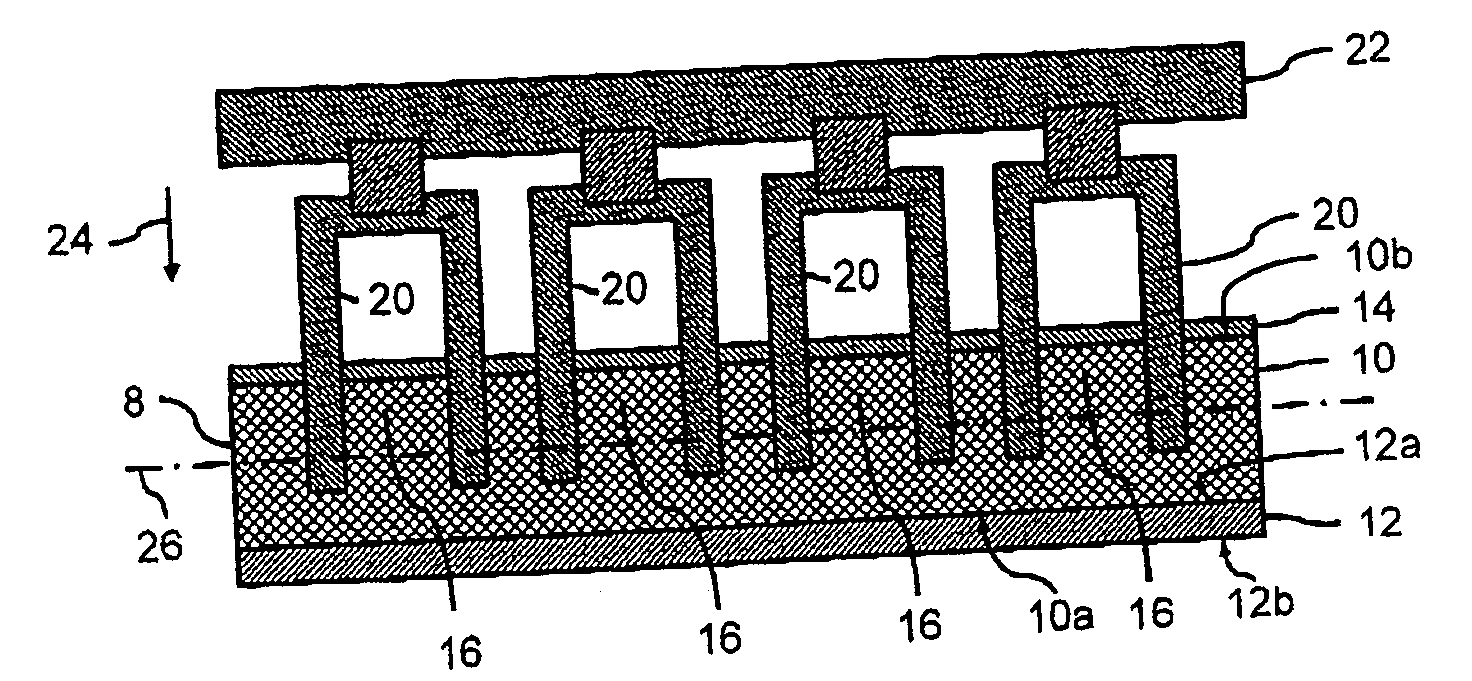
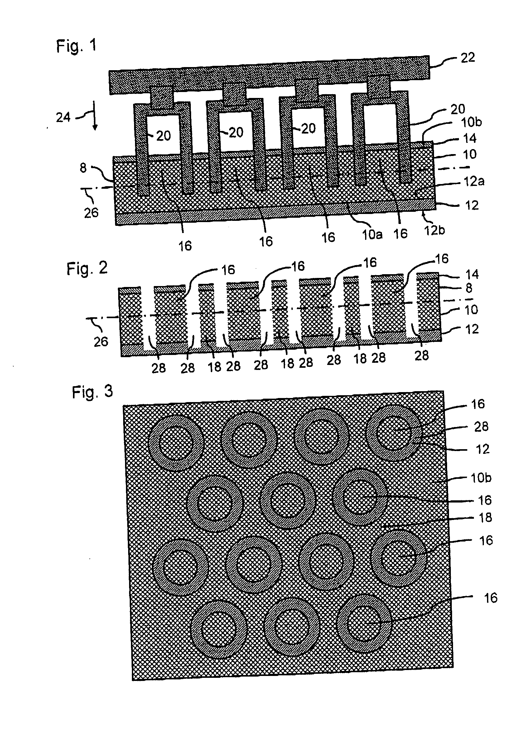
[0057]FIG. 1 shows a composite element 8 comprising a glass substrate 10 with a laminated-on plastic film 12, the lower surface 10a of the glass substrate 10 and the upper surface 12a of the plastic film 12 being releasably surface-joined to one another. A protective resist 14 has been applied to an upper surface 10b of the substrate 10. The composite element 8 can be placed, for example, onto a work table by means of a lower surface 12b of the carrier film 12.

[0058] Four hollow-cylindrical lapping punches 20 arranged next to one another are excited to ultrasonic vibration by a Sonotrode via a common holder 22 and are subjected to the action of force in the direction indicated by the arrow 24. The lapping punches 20, on account of their shape, remove the material of the protective resist 14, of the substrate 10 and of the carrier film 12 in portions, or specifically in the shape of circular rings, in order to punch a multiplicity of components 16 out of the substrate 10. The substr...


PUM

PropertyMeasurementUnit
Forceaaaaaaaaaa
Surfaceaaaaaaaaaa

Abstract

The invention relates to a process for producing components, in particular small glass plates, for example as windows for optical caps for optical components. It is an object to provide an inexpensive process which ensures a high surface quality of the components. The process according to the invention comprises the steps of: providing a substrate (10), providing a carrier (12), joining a first surface (10a) of the substrate (10) to a first surface (12a) of the carrier (12), for example by laminating on a carrier film, machining the components (16) out of the substrate (10), for example by means of ultrasonic vibratory lapping or sand-blasting, with the components (16) being held together by the carrier (12) at least immediately after the machining-out step, and detaching the components (16) from the carrier (12) in order to separate the components (16).

Description

FIELD OF THE INVENTION [0001] The invention relates to a process for producing a plurality of separate components in general, and to a process for producing small glass plates, for example windows for optical components, in particular. BACKGROUND OF THE INVENTION [0002] Glass is suitable for use as a contact material or covering material in many application areas. However, glass is difficult to machine, which is disadvantageous in particular if very small components, such as for example windows for optical caps, are to be produced. [0003] Conventional glass-machining techniques, such as scoring and breaking, are difficult to use for such applications, on account of the component size. Furthermore, the abovementioned techniques require subsequent edge machining, which may under certain circumstances have to be carried out individually, which entails considerable costs. [0004] In order nevertheless to keep the costs of these processes within acceptable limits, it is typical to work us...

Claims


Application Information

Patent Timeline
IPC IPC(8): H01L23/48B24B1/04B28D5/04
CPCB28D5/047B24B1/04
Inventor VOS, MARKUS
Owner SCHOTT AG
Why Eureka
Try Eureka