Driving method of display device

Inactive Publication Date: 2007-07-26
SEMICON ENERGY LAB CO LTD
View PDF66 Cites 15 Cited by
  • Summary
  • Abstract
  • Description
  • Claims
  • Application Information

AI Technical Summary

Benefits of technology

[0025]According to one aspect of the present invention, pseudo contours can be reduced by a plurality of middle-order sub-frames which has a middle-degree weighting and is used for an overlapping time gray scale method. Further, increase in the total number of sub-frames can be suppressed by at least one high-order sub-frame which has a larger weighting than that of the middle-order sub-frame and is used for a binary code time gray scale method. In addition, fine gray scales (that is, there is only a small difference between adjacent gray scales) can be efficiently displayed by at least one low-order sub-frame which has a smaller weighting than that of the middle-order sub-frame and is used for a binary code time gray scale method.
[0026]According to another aspect of the present invention, a first sub-frame group including a plurality of sub-frames which has the same weighting and is driven with an overlapping time gray scale method, and a second sub-frame group including a plurality of sub-frames which has a smaller weighting than that of the sub-frame in the first sub-frame group are included. In a case where a second sub-frame group is arranged so that the sub-frames therein are adjacently arranged in one frame to form a sub-frame region, every time the sub-frames in the second sub-frame group are turned from an all-lighting state to an all-non-lighting state in ac

Problems solved by technology

As described above, various methods for reducing pseudo contours have been proposed; however, the effect of reducing pseudo contours is not sufficient yet.
Therefore, the number of bits

Method used


Image

  • Driving method of display device
  • Driving method of display device
  • Driving method of display device

Examples


embodiment mode 1

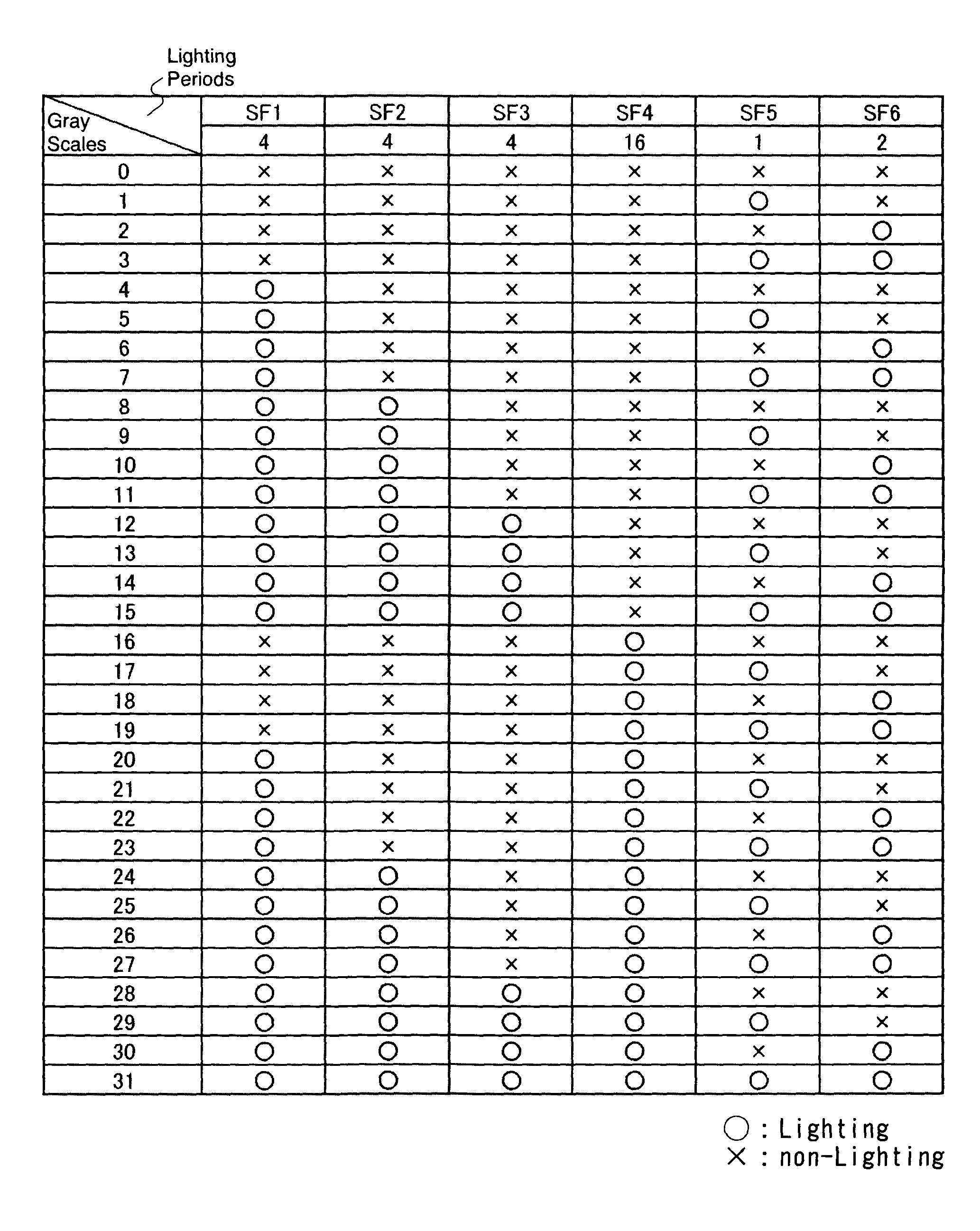
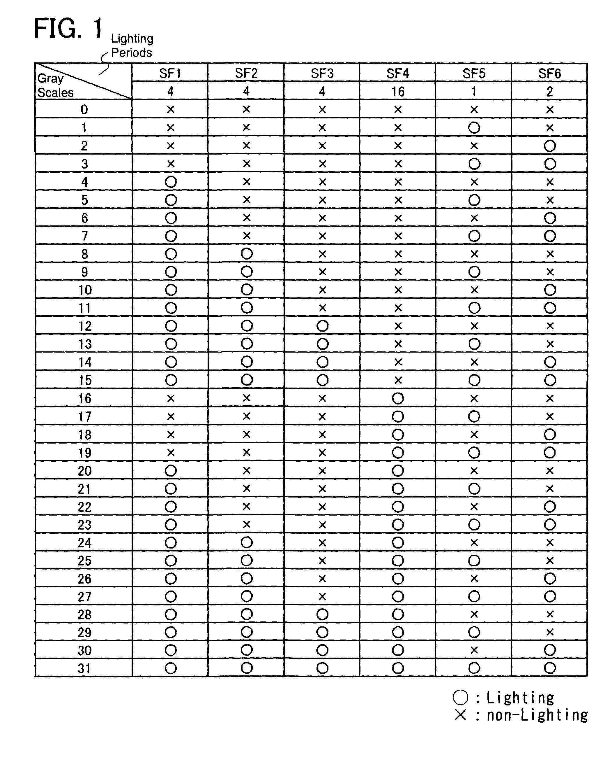
[0066]FIG. 1 is a diagram showing a lighting pattern of a sub-frame based on a preferred embodiment mode of the present invention. This embodiment mode has, in order that 32 (25) gray scales of gray scales of 0 to 31 are displayed, three middle-order sub-frames SF1 to SF3 each of which has the same middle-degree weighting (4) and is driven with an overlapping time gray scale method; a highest-order sub-frame SF4 which has a large weighting (16); and two low-order sub-frames SF5 and SF6 each of which has a small weighting (1, 2) and is driven with a binary code time gray scale method. As with a conventional example, also in this embodiment mode, various gray scales can be displayed by selectively lighting the sub-frames SF1 to SF6. It is to be noted that the lighting order of the sub-frames in one frame can take various modes, that is, the order may be the order from SF1 to SF6; from a sub-frame having a small weighting to a sub-frame having a large weighting, or the reverse; random;...

embodiment mode 2

[0103]In this embodiment mode, an example of a timing chart will be described. Although FIG. 1 is used as an example of a selecting method of sub-frames, the present invention is not limited thereto, and can easily be applied to other selecting method of sub-frames, other numbers of gray scales, or the like.

[0104]In addition, although the order in which sub-frames appear is SF1, SF2, SF3, SF4, SF5, and SF6 as an example, the present invention is not limited thereto and can easily be applied to other orders.

[0105]FIG. 16 shows a timing chart in a case where a period where signals are written to a pixel and a period where a pixel is lighted are separated. First, signals for one screen are inputted to all pixels in a signal-writing period. During this period, pixels are not lighted. After the signal-writing period, a lighting period starts and pixels are lighted. The length of the lighting period at this time is 1. Next, a subsequent sub-frame starts and signals for one screen are inpu...

embodiment mode 3

[0143]In this embodiment mode, an example of a display device using a driving method of the present invention will be described.

[0144]As a typical display device, a plasma display can be given. A pixel of a plasma display can be only in a light-emitting state or a non-light-emitting state. Accordingly, a time gray scale method is used as one of the means for achieving multiple gray scales. Therefore, the present invention is applicable thereto.

[0145]It is to be noted that, in a plasma display, initialization of a pixel is required as well as writing of a signal to a pixel. Therefore, it is desirable that sub-frames be sequentially arranged in the portion where the overlapping time gray scale method is used, and sub-frames using the binary code time gray scale method not be sandwiched therebetween. By thus arranging the sub-frames, the number of times of initialization of a pixel can be reduced. As a result, the contrast can be improved.

[0146]When sub-frames using the binary code tim...


PUM


Abstract

It is an object to provide a driving method of a display device capable of reducing pseudo contours while increase in the number of sub-frames is suppressed as much as possible. In a driving method of a display device where one frame is divided into a plurality of sub-frames to display a gray scale, the plurality of sub-frames has a plurality of middle-order sub-frames each of which has a middle-degree weighting and is used for an overlapping time gray scale method, at least one high-order sub-frame which has a larger weighting than that of the middle-order sub-frame and is used for a binary code time gray scale method, and at least one low-order sub-frame which has a smaller weighting than that of the middle-order sub-frame and is used for a binary code time gray scale method.

Description

BACKGROUND OF THE INVENTION[0001]1. Field of the Invention[0002]The present invention relates to a driving method of a display device, in particular, a driving method of a display device using a time gray scale method.[0003]2. Description of the Related Art[0004]In recent years, research and development of an active matrix display device using digital video signals have been actively carried out. There are, for example, a light receiving display device like a liquid crystal display (LCD) and a self-light-emitting display device like a plasma display in such an active matrix display device. As a light-emitting element used for the self-light-emitting display device, an organic light-emitting diode (OLED) has been attracting attention. The OLED is also referred to as an organic EL element, an electro luminescence (EL) element, or the like (a display using an EL element is referred to as an EL display). The self-light-emitting display device using the OLED or the like has advantages su...

Claims


Application Information

Patent Timeline
IPC IPC(8): G09G5/10H05B44/00
CPCG09G3/2029G09G2320/0266G09G3/3208G09G3/2033G09G3/20G09G3/36G09G3/296G09G3/30
Inventor KIMURA, HAJIME
Owner SEMICON ENERGY LAB CO LTD
Why Eureka
Try Eureka