
Structure of illumination apparatus

Inactive Publication Date: 2005-04-12
INNOLUX CORP
View PDF3 Cites 6 Cited by
  • Summary
  • Abstract
  • Description
  • Claims
  • Application Information

AI Technical Summary

Benefits of technology

For the forgoing reasons, it is therefore an objective of the present invention to provide a structure of an illumination apparatus for generating uniform planar light, increasing brightness and increasing illumination efficiency of a liquid crystal display.
Another objective of the present invention is to provide a structure of an illumination apparatus that increases brightness of a liquid crystal display without further increasing the volume of the LCD.

Problems solved by technology

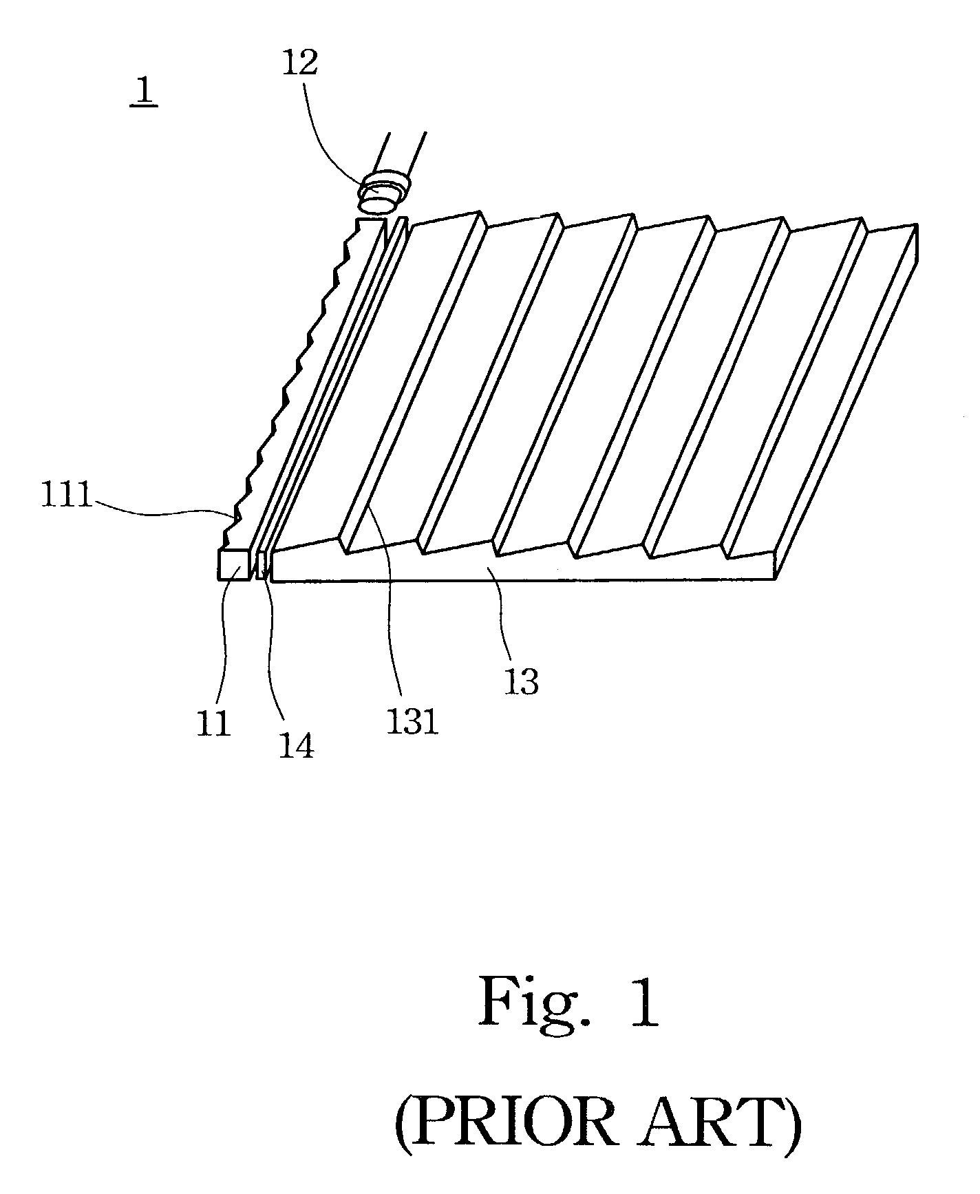
However, large-sized panel products face the problems of how to generate uniform planar light projected onto the liquid crystal display panel, how to provide enough brightness and how to increase illumination efficiency of a LCD.
In this design, extraordinary light sources cannot be added so that the design cannot be applied in the large-sized panel LCD products which require high brightness.
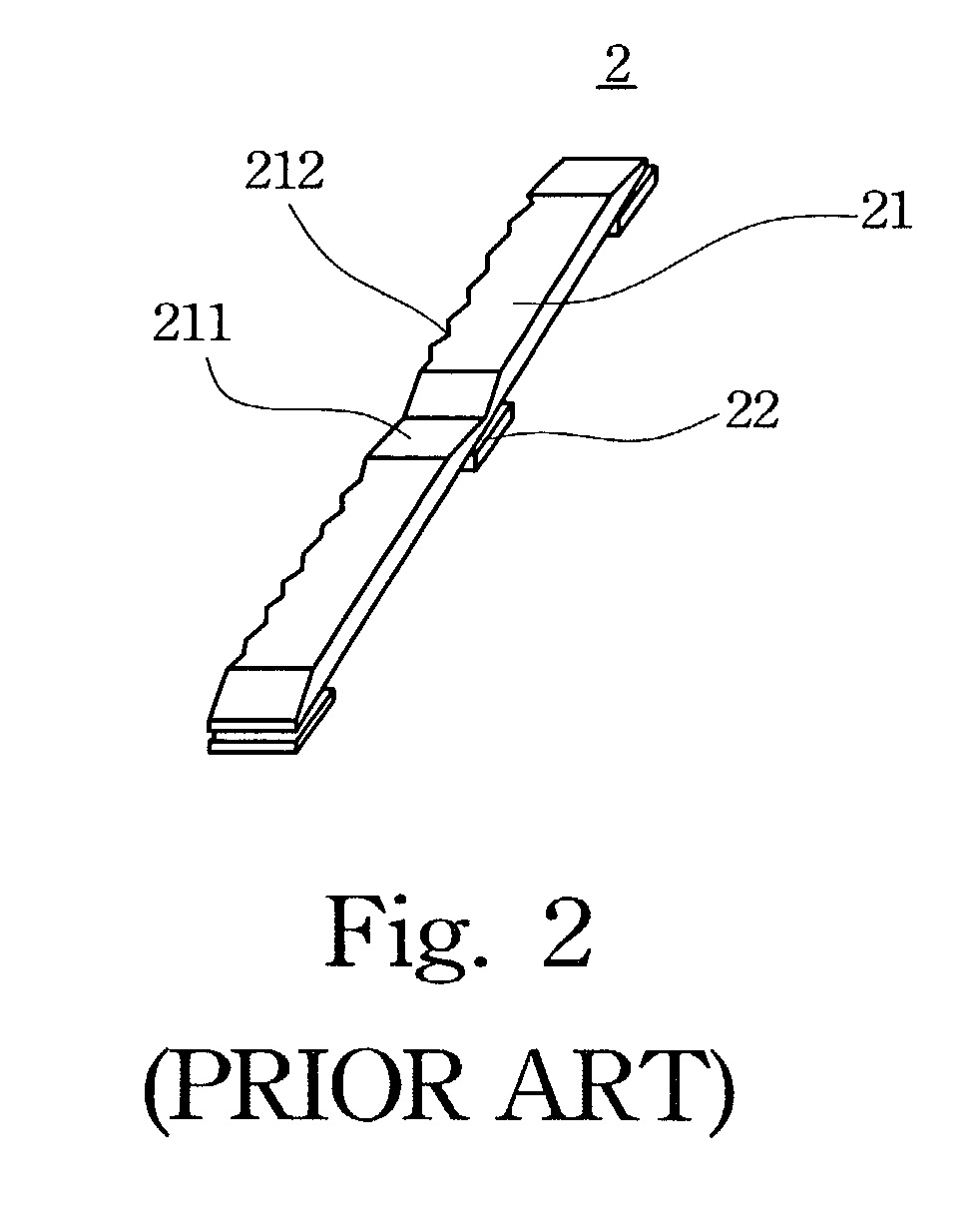
Although this kind of design can increase the number of the located light sources, existence of the tilt planes 211 still limits the number of the light sources 22.
This structure also cannot be applied in the large-sized panel LCD products.

Method used


Image

  • Structure of illumination apparatus
  • Structure of illumination apparatus
  • Structure of illumination apparatus

Examples


first embodiment

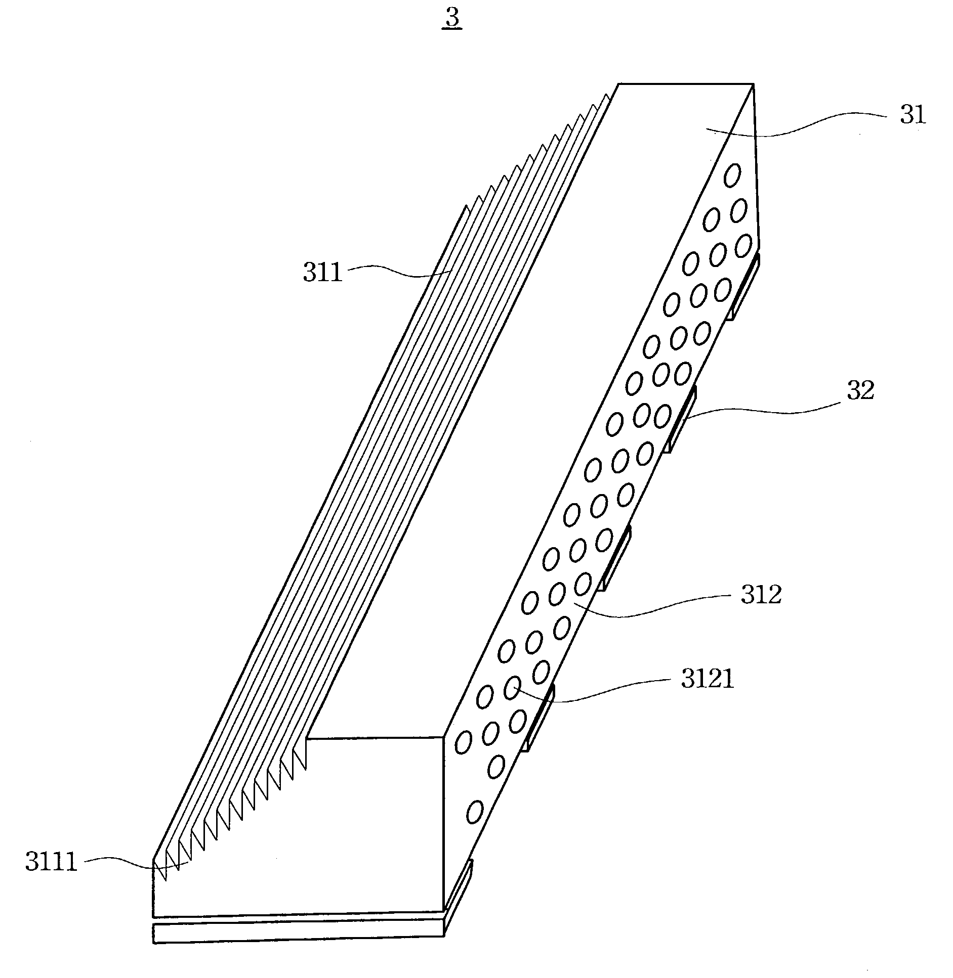
Reference is made to FIG. 3A, which is a schematic view showing a structure of an illumination apparatus 3 in accordance with the present invention. The illumination apparatus 3 includes a light guide rod 31 having at least one tilt plane 311 and plural light sources 32 located below the light guide rod 31. The tilt plane 311 directly guides light emitted from the light sources 32 to the light guide plate 4 as shown in FIG. 4. Preferably, the light sources 32 are separated by an equal distance, and each light source 32 can be a spot light source, e.g. light emitting diode (LED).

second embodiment

Reference is made to FIG. 3B, which is a schematic view showing a structure of an illumination apparatus 3 in accordance with the present invention. According to the illumination apparatus 3 of the present invention, a plurality of horizontal notches 3111 can be further formed in the tilt plane 311 to increase illumination efficiency of the LCD. In addition, a plurality of dispersion dots 3121 can be further formed on an out-going plane 312 of the light guide rod 31 for dispersing light emitted from the light guide rod 31 to the light guide plate 4 as shown in FIG. 4.

The dispersion dots 3121 can be depressed dispersion dots or protruding dispersion dots. The depressed dispersion dots can be integrally formed with the light guide rod 31 or by an etching step. Protruding dispersion dots can be formed integrally with the light guide rod 31 or by a dipping step. Preferably, the protruding dispersion dots are made of transparent resin or other equivalent material which can achieve the fu...


PUM


Abstract

A structure of an illumination apparatus is described. The structure has a light guide rod arranged at one lateral side of a light guide plate, and plural light sources located below the light guide rod. The light guide rod has at least one tilt plane formed thereon in order to guide the light emitted from the light sources to the light guide plate such that uniform planar light could be generated therefrom. A plurality of notches is formed in the tilt plane, and a plurality of depressed or protruding dispersion dots is formed on an out-going plane of the light guide rod. The structure further includes an anti-reflection layer positioned between the light guide rod and the light guide plate.

Description

BACKGROUND OF THE INVENTION1. Field of InventionThe present invention relates to a structure of an illumination apparatus. More particularly, the present invention relates to a structure of an illumination apparatus for generating uniform planar light, increasing brightness and increasing illumination efficiency of a liquid crystal display.2. Description of Related ArtLiquid crystal display (LCD) has so many advantages, including high picture quality, small volume, light weight, low driving voltage and low power consumption, that LCDs are widely applied in electronic products such as medium or small-sized portable televisions, mobile phones, videos, notebooks, and monitors for desktop computers and projection-type televisions. Therefore, as time goes by, LCDs are gradually replacing cathode ray tube (CRT) monitors.The present LCDs are not applied only in medium-sized or small-sized panel LCD products, such as small-sized portable televisions, mobile phones, videos, notebooks and mon...

Claims


Application Information

Patent Timeline
IPC IPC(8): F21V8/00
CPCG02B6/0018G02B6/0048G02B6/0028
Inventor MAI, CHE-KUEILIN, HONG-YU
Owner INNOLUX CORP
Learn More