Lithium secondary battery

Active Publication Date: 2007-07-26
PANASONIC CORP
View PDF6 Cites 13 Cited by
  • Summary
  • Abstract
  • Description
  • Claims
  • Application Information

AI Technical Summary

Benefits of technology

[0006]An object of the present invention is to achieve both excellent safety and high output power in a lithium secondary battery in which a current co

Problems solved by technology

Accordingly, it is difficult to achieve lithium secondary batteries having high output power.
This may cause the adjacent s

Method used


Image

  • Lithium secondary battery
  • Lithium secondary battery
  • Lithium secondary battery

Examples


example 1

[0064](i) Production of Positive Electrode

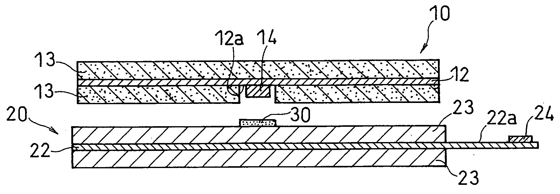
[0065]A positive electrode material mixture paste was prepared by mixing 3 kg of lithium cobalt oxide with 1 kg of PVDF#1320 (an N-methyl-2-pyrrolidone (NMP) solution containing 12 wt % PVDF) available from Kureha Chemical Industry Co., Ltd., 90 g of acetylene black and an appropriate amount of NMP with the use of a double arm kneader. This paste was applied onto each entire surface of a 15 μm thick aluminum foil serving as a positive electrode current collector 12 except for a center exposed portion 12a, which was then dried and rolled to form positive electrode active material layers 13, each having an active material density of 3.5 g / cm3 and a thickness of 80 μm. The positive electrode current collector 12 was cut into a strip having a size of 600 mm×56 mm. Thereby, a positive electrode 10 was obtained. The center exposed portion 12a having a width of 15 mm was positioned exactly at the center in a longitudinal direction of the positive e...

example 2

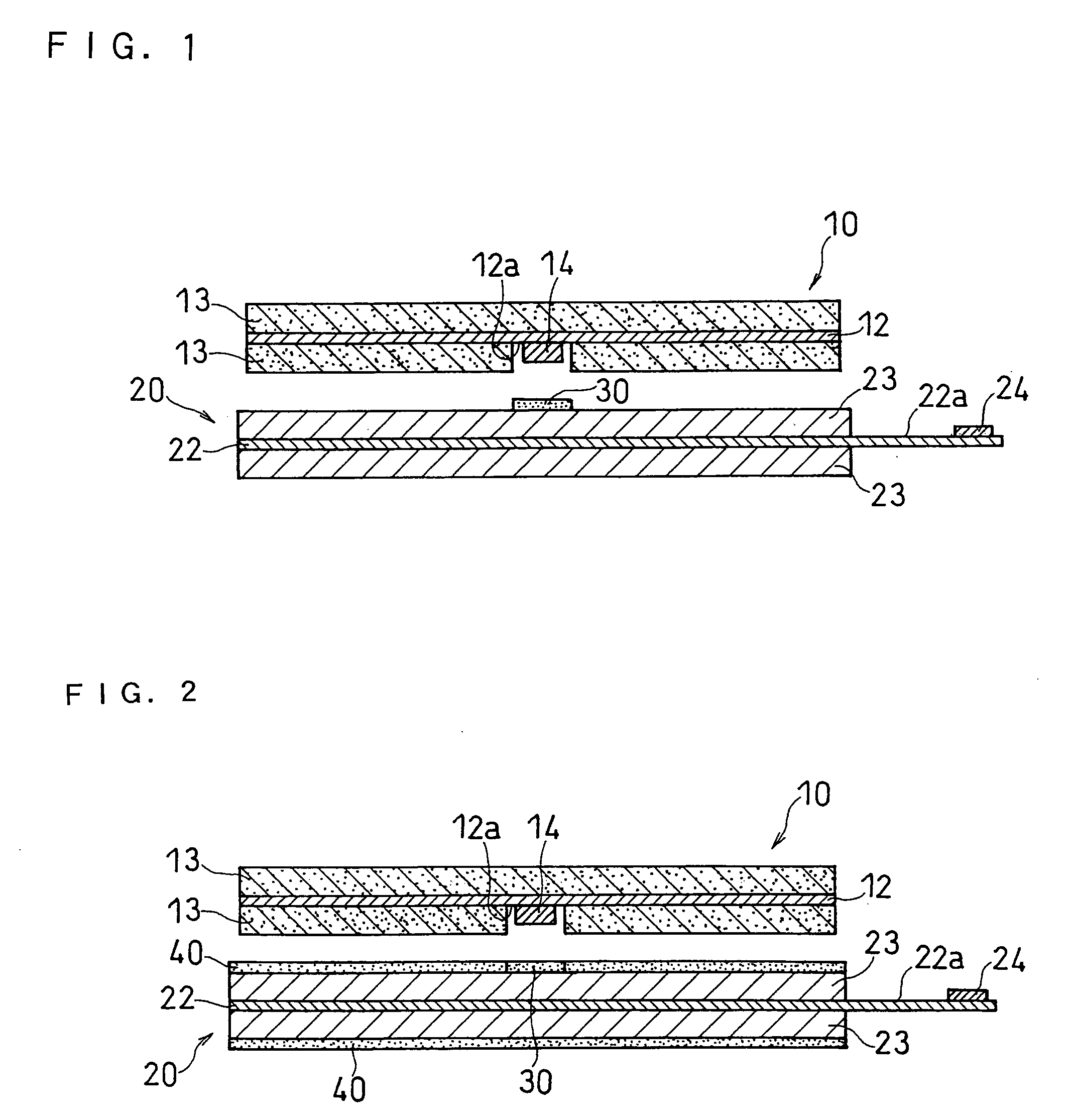
[0071]As shown in FIG. 2, a lithium secondary battery was produced in the same manner as in EXAMPLE 1 except that a second heat resistant layer 40 was further formed using the same precursor paste as used for the first heat resistant layer in EXAMPLE 1. Specifically, in this example, in addition to the first heat resistant layer 30, a second heat resistant layer having a thickness of 5 μm was formed on the negative electrode active material layer 23 such that the second heat resistant layer faced the almost entire surface of the positive electrode active material layer 13. Similar to the first heat resistant layer 30, the second heat resistant layer 40 was formed by applying the precursor paste onto the negative electrode active material layer by a gravure roll.

example 3

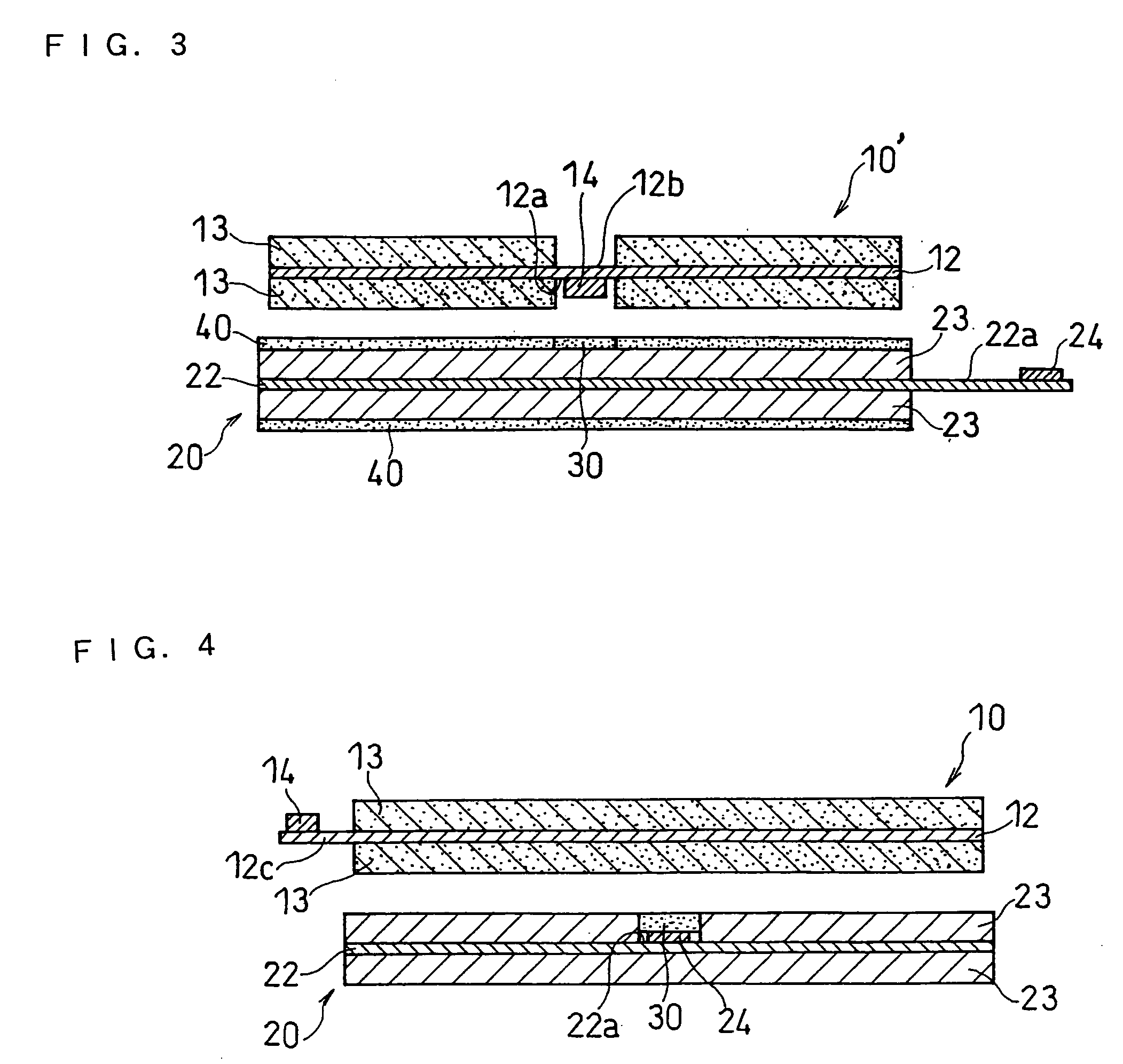
[0072]A lithium secondary battery was produced in the same manner as in EXAMPLE 1 except that the first heat resistant layer was directly formed on the positive electrode 10 such that the first heat resistant layer covered the center exposed portion 12a having the positive electrode current collecting lead 14 connected thereto.


PUM


Abstract

A lithium secondary battery including: a positive electrode including a strip-shaped positive electrode current collector and a positive electrode active material layer carried on each surface of the positive electrode current collector; a negative electrode including a strip-shaped negative electrode current collector and a negative electrode active material layer carried on each surface of the negative electrode current collector; a separator interposed between the positive electrode and the negative electrode; and a non-aqueous electrolyte, wherein an exposed portion carrying no active material layer is formed on a substantially center portion in a longitudinal direction of at least one of the positive electrode current collector and the negative electrode current collector, a current collecting lead is connected to the exposed portion, and a first heat resistant layer is formed such that the first heat resistant faces at least part of the current collecting lead.

Description

FIELD OF THE INVENTION[0001]The present invention relates to a lithium secondary battery, and more particularly to a lithium secondary battery having both excellent safety and high output power.BACKGROUND OF THE INVENTION[0002]Lithium secondary batteries, which are light in weight and have a high energy density, are widely used commercially as a power source for portable devices. Currently, lithium secondary batteries are also receiving considerable attention as a possible power source capable of offering high output power for large-scale applications (e.g., a power source for vehicles) and are now under active development.[0003]The electrolytes for use in lithium secondary batteries, however, are usually non-aqueous electrolytes prepared by dissolving a lithium salt in a non-aqueous solvent. Non-aqueous electrolytes have lower ionic conductivity than electrolytes comprising an aqueous solution. Accordingly, it is difficult to achieve lithium secondary batteries having high output p...

Claims


Application Information

Patent Timeline
IPC IPC(8): H01M4/64H01M2/16H01M4/13H01M10/0525H01M10/36H01M50/449H01M50/451H01M50/474H01M50/486H01M50/489H01M50/536
CPCH01M2/14H01M2/1673H01M2/1686H01M2/26Y02T10/7011H01M4/70H01M10/044H01M10/0525Y02E60/122H01M4/13Y02E60/10H01M50/46H01M50/449Y02P70/50H01M50/451H01M50/486H01M50/489H01M50/474H01M50/536A24F15/005Y02T10/70
Inventor FUJIKAWA, MASATOINOUE, KAORUSHIMADA, MIKINARI
Owner PANASONIC CORP
Why Eureka
Try Eureka