

Pneumatic tire
- Summary
- Abstract
- Description
- Claims
- Application Information
AI Technical Summary
Benefits of technology
Problems solved by technology
Method used
Image

Examples
examples
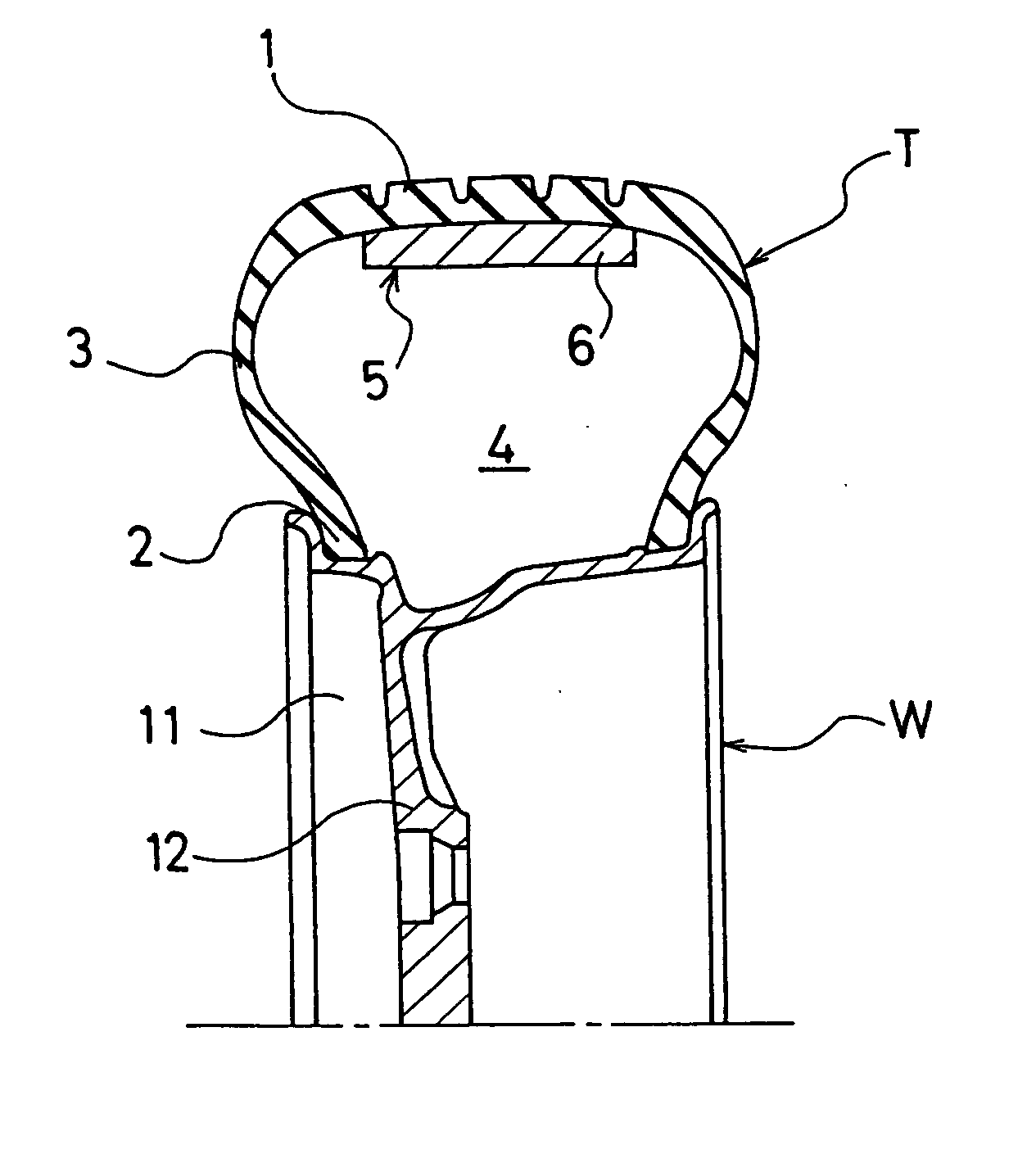
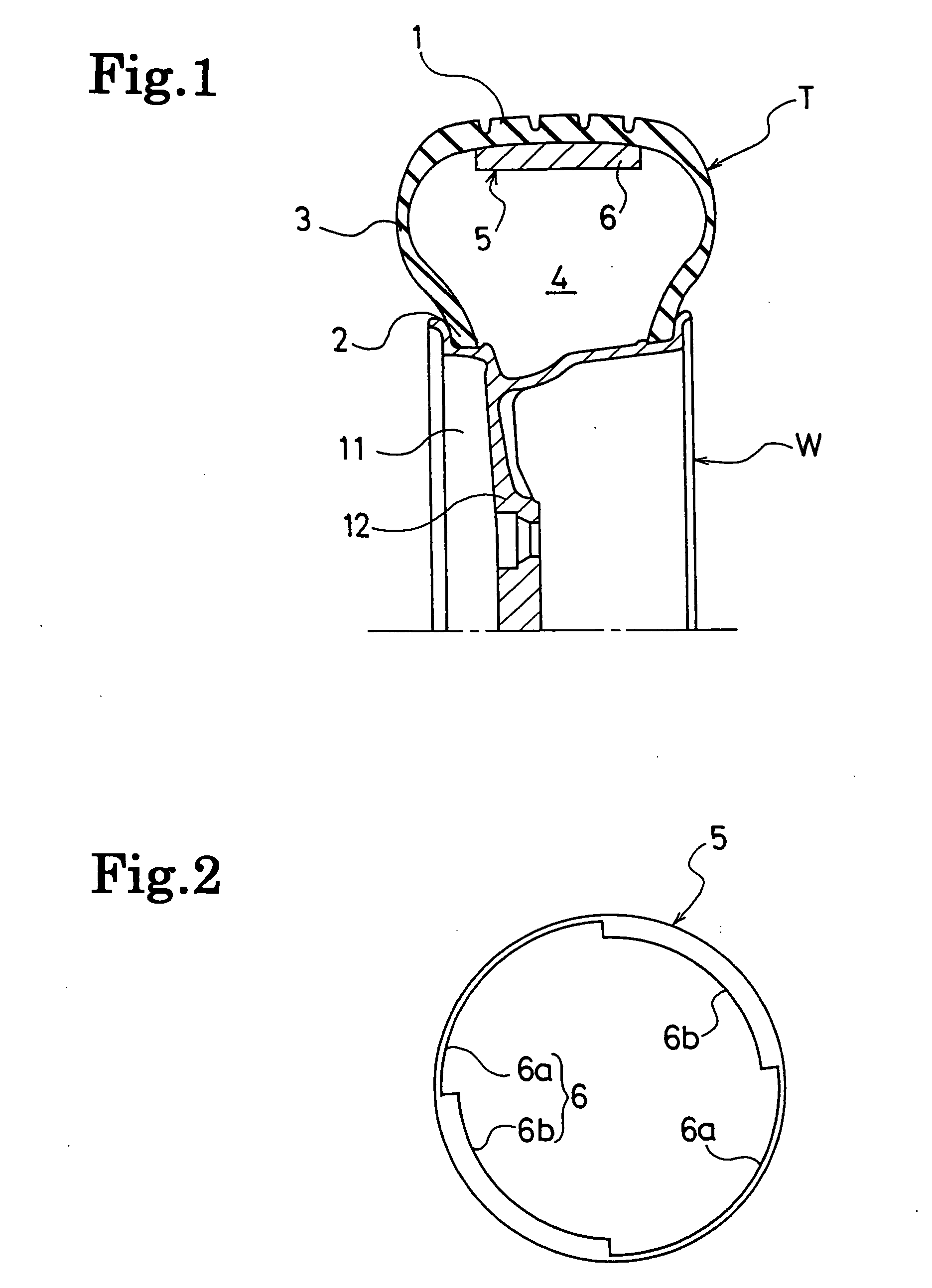
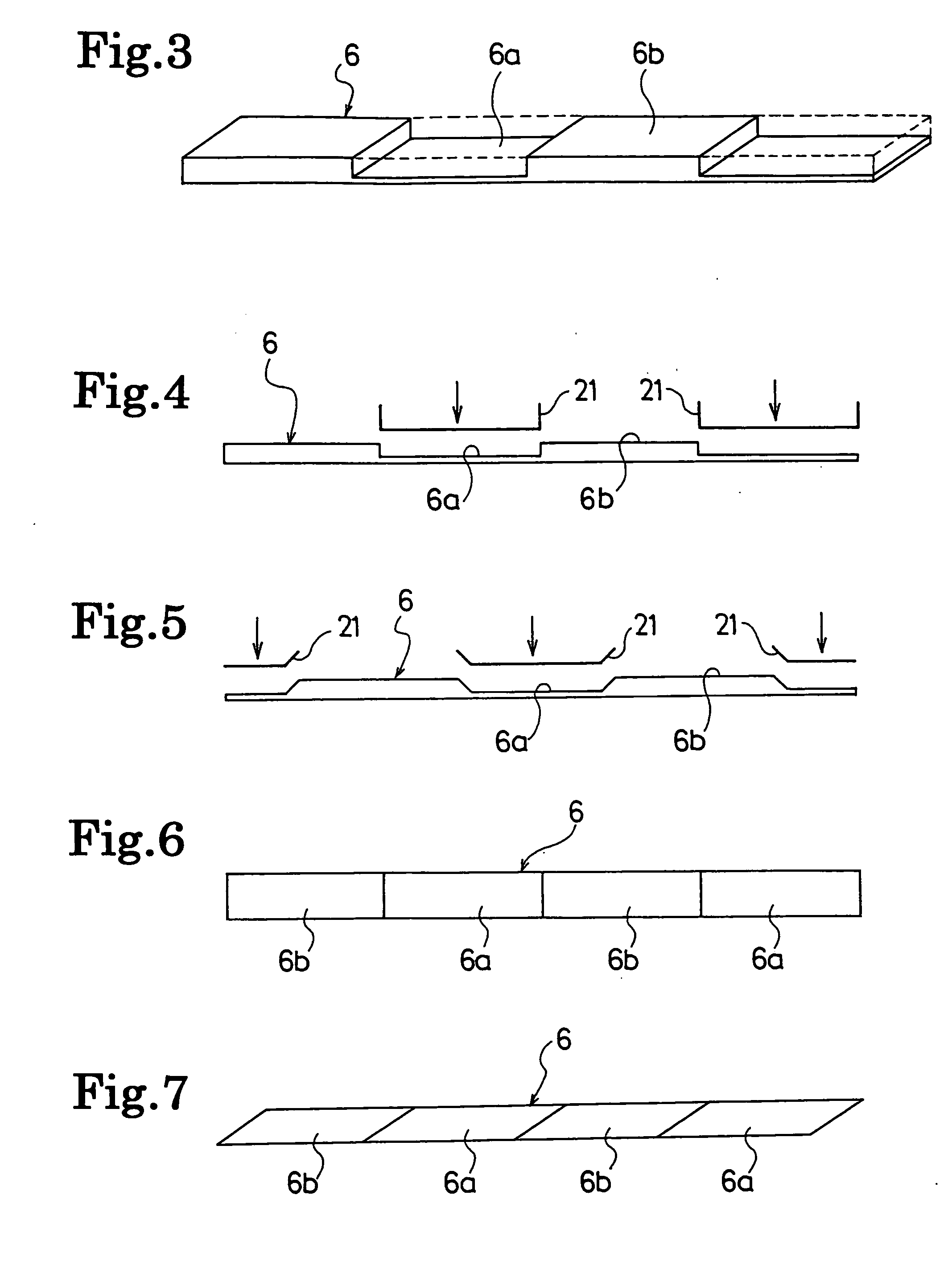
[0037] Tires of Conventional Example, Example, and Comparative Example were respectively manufactured. These tires are pneumatic tires each having a tire size of 215 / 60R16, which are only different from one another in conditions for the cavity portion. The tire of Conventional Example is one where nothing was disposed in a cavity portion thereof. The tire of Example is one where, by configuring an annular object (refer to FIG. 2) having cross-sectional areas which vary by partially applying compression forming to a porous material (polyurethane foam) member with a density of 20 kg / m3 and with an uniform cross-sectional shape in the tire circumferential direction, this annular object was mounted on an inside surface of a tread portion. While the difference between the maximum value Smax and the minimum value Smin of the cross-sectional areas of the porous material member was set at 16% of the cross-sectional area of the cavity portion of the tire, the maximum value Tmax and the minim...
PUM
 Abstract
Description
Claims
Application Information