
Control device and control method for vehicle

Inactive Publication Date: 2007-08-02
HITACHI LTD
View PDF1 Cites 24 Cited by
  • Summary
  • Abstract
  • Description
  • Claims
  • Application Information

AI Technical Summary

Benefits of technology

[0007]An object of the present invention is to solve the above disadvantage concerning the lubricating oil in order to improve shift performance, safety a vehicle's fuel efficiency.
[0009]According to the present invention, in an automatic transmission using a power transfer mechanism which transfers and releases power while being lubricated with oil, shift performance and safety thereof are improved, and eventually a vehicle's fuel efficiency is improved.

Problems solved by technology

On the other hand, when the power transfer mechanism is released, the lubricating oil works as a source of drag torque, thereby bringing the disadvantage that may cause deterioration in fuel efficiency and shift performance.

Method used


Image

  • Control device and control method for vehicle
  • Control device and control method for vehicle
  • Control device and control method for vehicle

Examples


first embodiment

[0054]This embodiment illustrates an example of control for a wet clutch comprising a twin clutch mechanism being used for a twin clutch type automated MT.

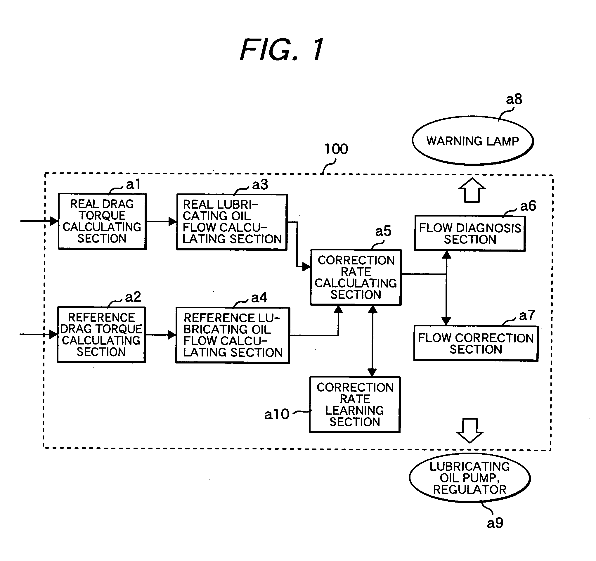
[0055]FIG. 1 is a block diagram of a control device as an embodiment of the present invention.

[0056]A power train control unit 100 as a control device includes: a real drag torque calculating section a1 which calculates the drag torque of a wet clutch in an actual vehicle; a reference drag torque calculating section a2 which calculates a preferable drag torque according to a wet clutch condition such as lubricating oil temperature, and rotation speed; a real lubricating oil flow rate calculating section a3 which calculates, from the real drag torque, a real flow rate of lubricating oil actually supplied to the wet clutch; a reference lubricating oil flow rate calculating section a4 which calculates a preferable reference flow rate of lubricating oil to be supplied to the wet clutch in order to attain the reference drag torque; a c...

second embodiment

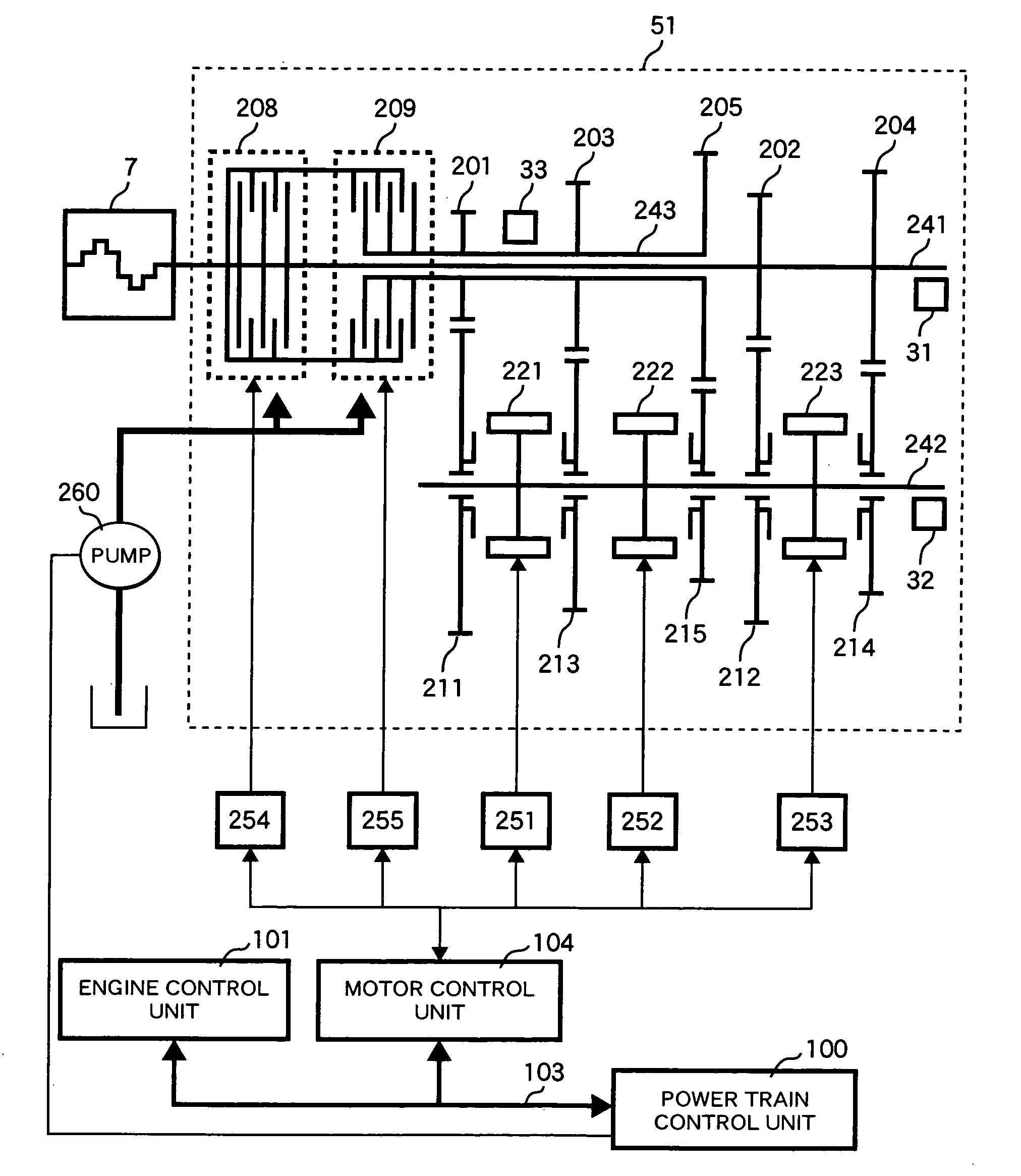
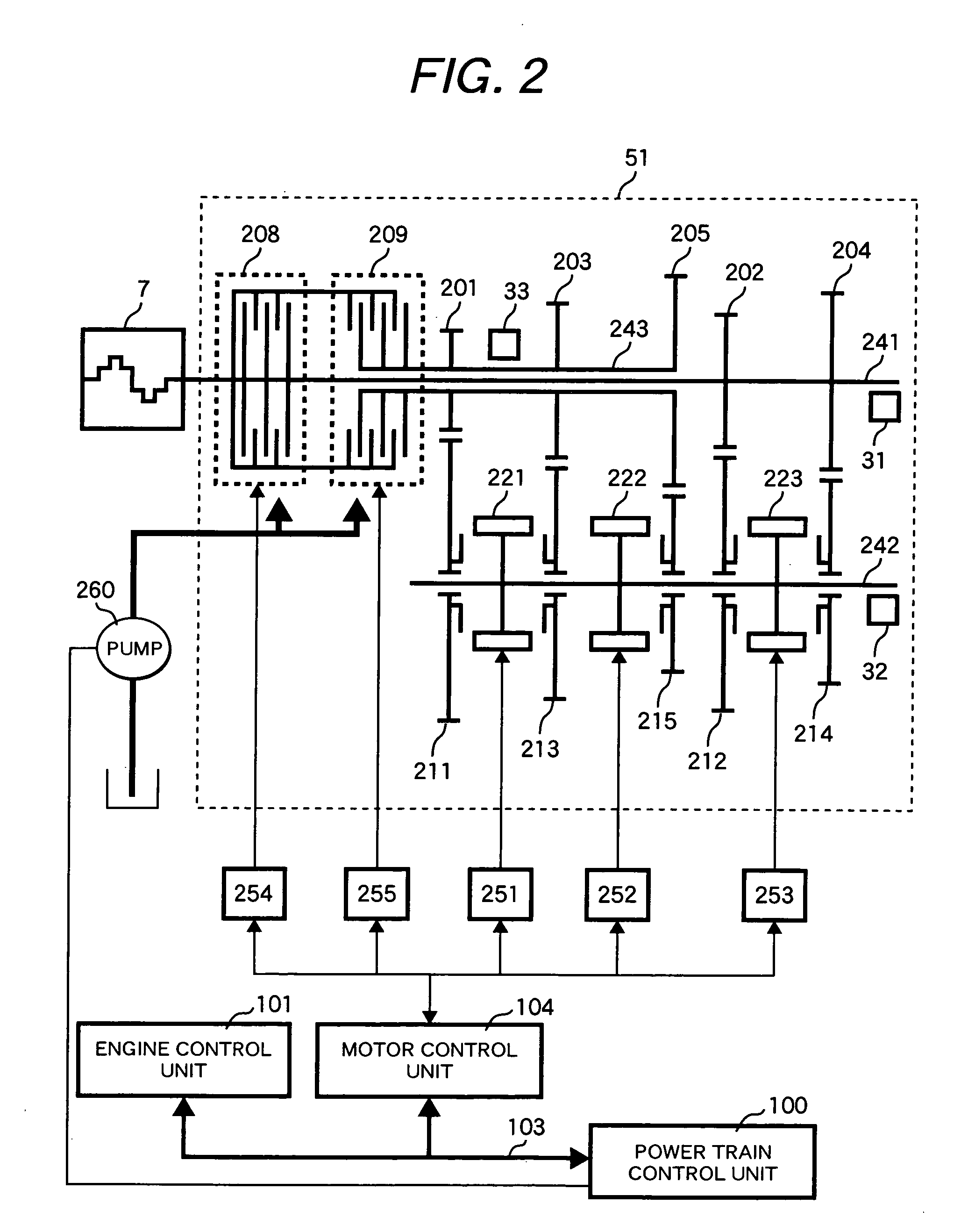
[0132]FIG. 20 is a skeleton diagram of an example of a second system configuration including a vehicle control device with an automatic transmission according to another embodiment of the present invention.

[0133]The same reference numerals as in FIG. 1 represent the same elements. This embodiment concerns a transfer with an assist clutch, a so-called torque assist type automatic transmission.

[0134]An automatic transmission 50 includes a clutch 8 for an input shaft, an assist clutch 9, an input shaft 41 for transmission, an output shaft 42, a first drive gear 1, a second drive gear 2, a third drive gear 3, a fourth drive gear 4, a fifth drive gear 5, a sixth drive gear 6, a first driven gear 11, a second driven gear 12, a third driven gear 13, a fourth driven gear 14, a fifth driven gear 15, a sixth driven gear 16, a first mesh type mechanism 21, a second mesh type mechanism 22, a third mesh type mechanism 23, a rotation sensor 31 and a rotation sensor 32.

[0135]The engine 7 is connec...


PUM


Abstract

A vehicle control device includes: real drag torque calculating means a1 which calculates the drag torque of a power transfer mechanism; lubricating oil flow rate calculating means a3 which determines the flow rate of lubricating oil according to an real drag torque; reference drag torque calculating means a2 which calculates a reference drag torque as a reference; reference lubricating oil flow rate calculating means a4 which calculates a reference lubricating oil flow rate according to the reference drag torque; correction rate calculating means a5 which calculates a correction value corresponding to the rate of correction of the lubricating oil flow rate according to the lubricating oil flow rate and reference lubricating oil flow rate; and flow rate correction means a7 which outputs a drive signal to an actuator which controls the lubricating oil flow rate according to the correction rate.

Description

CLAIM OF PRIORITY[0001]The present application claims priority from Japanese application serial no. 2006-018359, filed on Jan. 27, 2006, the contents of which are hereby incorporated by references into this application.BACK GROUND OF THE INVENTION[0002]The present invention relates to a vehicle control device and a vehicle control method.[0003]Conventional types of automatic transmission for vehicles include one which uses a torque converter and one which uses a continuously variable transmission. Recently an automated MT (manual transmission) has been proposed. It is comprised of a system in which clutching and gear change are automated based on a manual transmission mechanism. A recent automated MT system in which a friction clutch (assist clutch) is provided between the input and output shafts of the transmission for keeping torque transfer during gear shift operation, is proposed (for example, see JP-A No. 2000-65199). Furthermore, a so-called twin clutch automated MT is propose...

Claims


Application Information

Patent Timeline
IPC IPC(8): B60W10/02B60W10/10F16H59/14F16H59/42F16H59/68F16H59/72F16H61/02F16H61/68F16H61/684F16H61/688
CPCF16D25/123F16H57/0473F16D2300/06F16D2500/1086F16D2500/30803F16D2500/30805F16D2500/3166F16D2500/5029F16D2500/5108F16D2500/70448F16H57/0434F16H61/0021F16H61/688F16H2061/0037Y10T74/19991F16D48/066
Inventor YOSHIDA, YOSHIYUKIMATSUMURA, TETSUOSHISHIDO, KENTARO
Owner HITACHI LTD
Features
  • Generate Ideas
  • Intellectual Property
  • Life Sciences
  • Materials
  • Tech Scout
  • Unparalleled Data Quality
  • Higher Quality Content
  • 60% Fewer Hallucinations
Learn More