System, method, and apparatus for metallic-composite joint with compliant, non-corrosive interface

a technology of compliant and non-corrosive interfaces and systems, applied in the direction of soldering apparatus, manufacturing tools,auxillary welding devices, etc., can solve the problems of difficult and tedious process of joining dissimilar materials such as metallic and composite components, and the failure of pi-shaped joints to form metallic-to-composite joints, etc., to prevent galvanic corrosion and reduce the risk of separation

Active Publication Date: 2007-08-02
LOCKHEED MARTIN CORP
View PDF13 Cites 15 Cited by
  • Summary
  • Abstract
  • Description
  • Claims
  • Application Information

AI Technical Summary

Benefits of technology

[0007] An inert compliant layer, such as titanium, is located between the legs of the preform and the metallic member. The compliant layer may be a sleeve-type member, coated on the metallic member, or applied by various other known techniques prior to insertion into the preform. The compliant layer also may be discontinuous. The resin binder or an adhesive may be used to bond the compliant layer to the preform. Advantageously, the compliant layer acts as a barrier to galvanic corrosion that might otherwise occur between the carbon in the preform and the metallic member. In addition, the compliant layer has a coefficient of thermal expansion that more closely matches that of the preform to reduce the risk of separation therebetween when subjected to thermal stresses. For example, the compliant layer primarily acts as a ductile layer to absorb the greater expansion of the metal against the lesser expansion of the composite as thermal energy is applied.

Problems solved by technology

Joining dissimilar materials such as metallic and composite components is a difficult and tedious process.
However, pi-shaped joints have not been used successfully to form metallic-to-composite joints because of thermal expansion mismatch and galvanic corrosion.

Method used


Image

  • System, method, and apparatus for metallic-composite joint with compliant, non-corrosive interface
  • System, method, and apparatus for metallic-composite joint with compliant, non-corrosive interface

Examples


Embodiment Construction

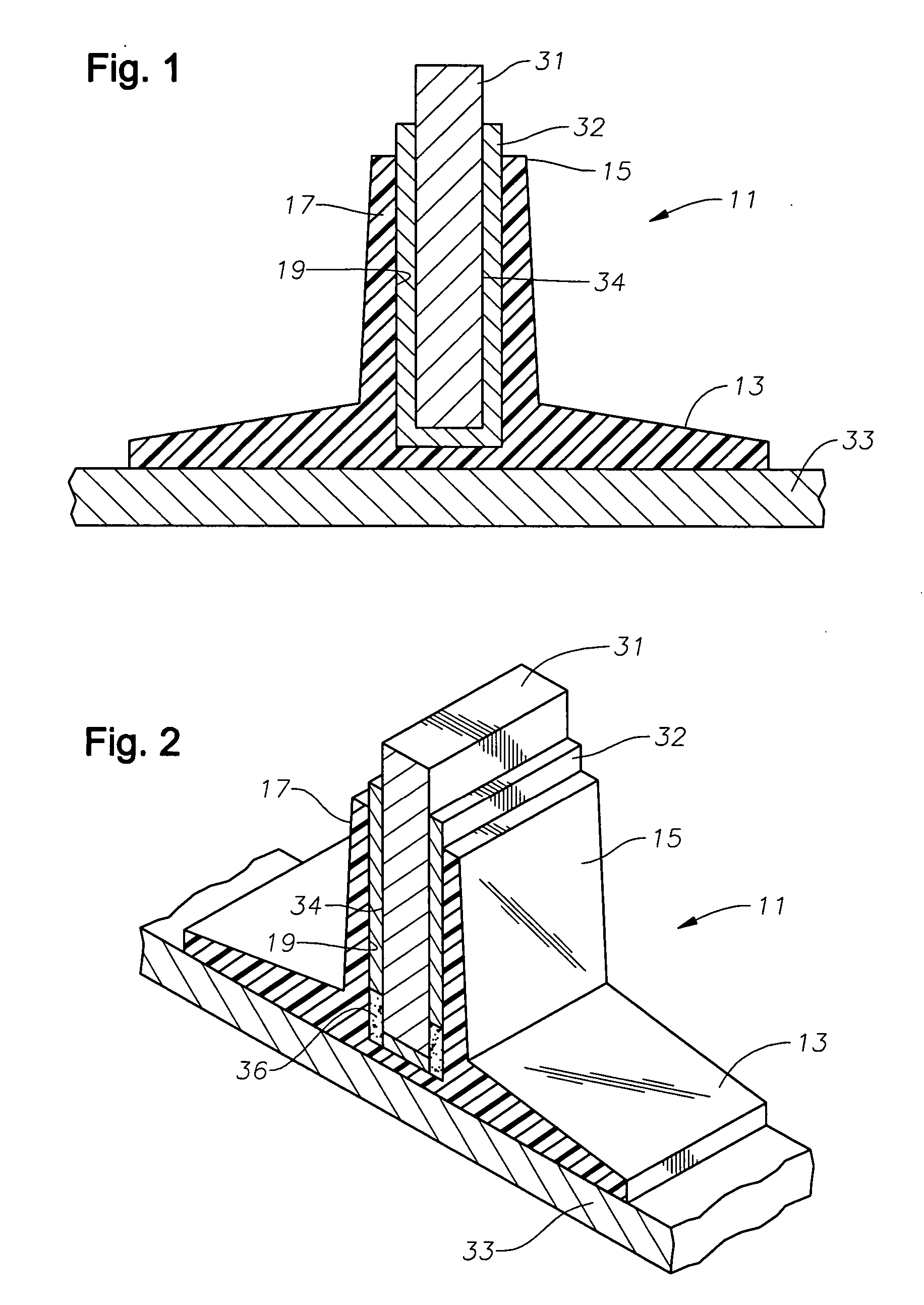
[0013] Referring to FIGS. 1 and 2, one embodiment of a system, method, and apparatus for forming a compliant, non-corrosive interface or joint between metallic and composite materials is shown. A preformed component or “preform”11 for a structural support beam is shown. When viewed from the end or in cross-section, preform 11 resembles the Greek letter “pi” having a longitudinal crossbar or base 13 with two longitudinal legs 15, 17 extending therefrom. A channel or slot 19 is defined between the base 13 and legs 15, 17.

[0014] In one embodiment, preform 11 is a composite material that is formed by weaving or braiding continuous bundles or tows of structural fibers. The tows of fibers may be oriented to extend continuously throughout each segment of preform 11 including base 13 and legs 15, 17. The fiber preforms may be formed to provide any desired fiber architecture needed to impart chosen load-carrying capability and to accommodate any desired web plate thickness. Preform 11 may b...


PUM

PropertyMeasurementUnit
metallicaaaaaaaaaa
coefficient of thermal expansionaaaaaaaaaa
thermal stressesaaaaaaaaaa

Abstract

A metallic-composite joint is formed by inserting a metallic member into a slot of a pi-shaped composite preform. The preform is formed from woven carbon fiber in a binder of resin and may or may not be cured prior to assembly. An inert compliant layer is located between the legs of the preform and the metallic member. The resin binder or an adhesive is used to bond the compliant layer to the preform. The compliant layer has a coefficient of thermal expansion that more closely matches that of the preform. The properties of the compliant layer also avoid galvanic corrosion between the carbon in the preform and the metallic member.

Description

BACKGROUND OF THE INVENTION [0001] 1. Technical Field [0002] The present invention relates in general to joining dissimilar materials at a structural interface and, in particular, to an improved system, method, and apparatus for forming a compliant, non-corrosive interface between metallic and composite materials. [0003] 2. Description of the Related Art [0004] Joining dissimilar materials such as metallic and composite components is a difficult and tedious process. There are many well known techniques for joining or forming joints between metallic materials. In the aerospace industries, composite components may be joined with prefabricated or preformed pi-shaped joints. For example, U.S. Pat. No. 6,718,713 to McKague describes a structural member having a planar base with two longitudinal legs extending in parallel from the base. A channel is defined between the legs for insertion of a flat plate that forms the first member of the structural member. The base of the preform is bonde...

Claims


Application Information

Patent Timeline
Patent Type & Authority Applications(United States)
IPC IPC(8): H01L21/00B23K37/00B23K35/12
CPCB23K35/02
Inventor BARNES, JOHN E.
Owner LOCKHEED MARTIN CORP
Why Eureka
Try Eureka