

Connector-and-tube assembly and method for forming the same
- Summary
- Abstract
- Description
- Claims
- Application Information
AI Technical Summary
Benefits of technology
Problems solved by technology
Method used
Image

Examples
first embodiment
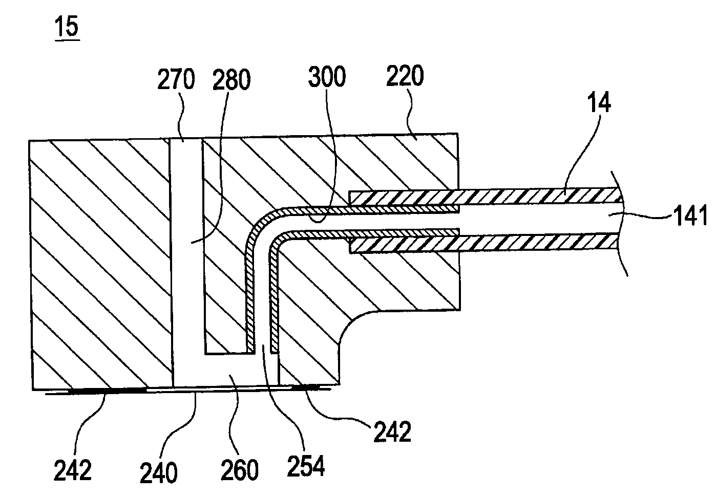
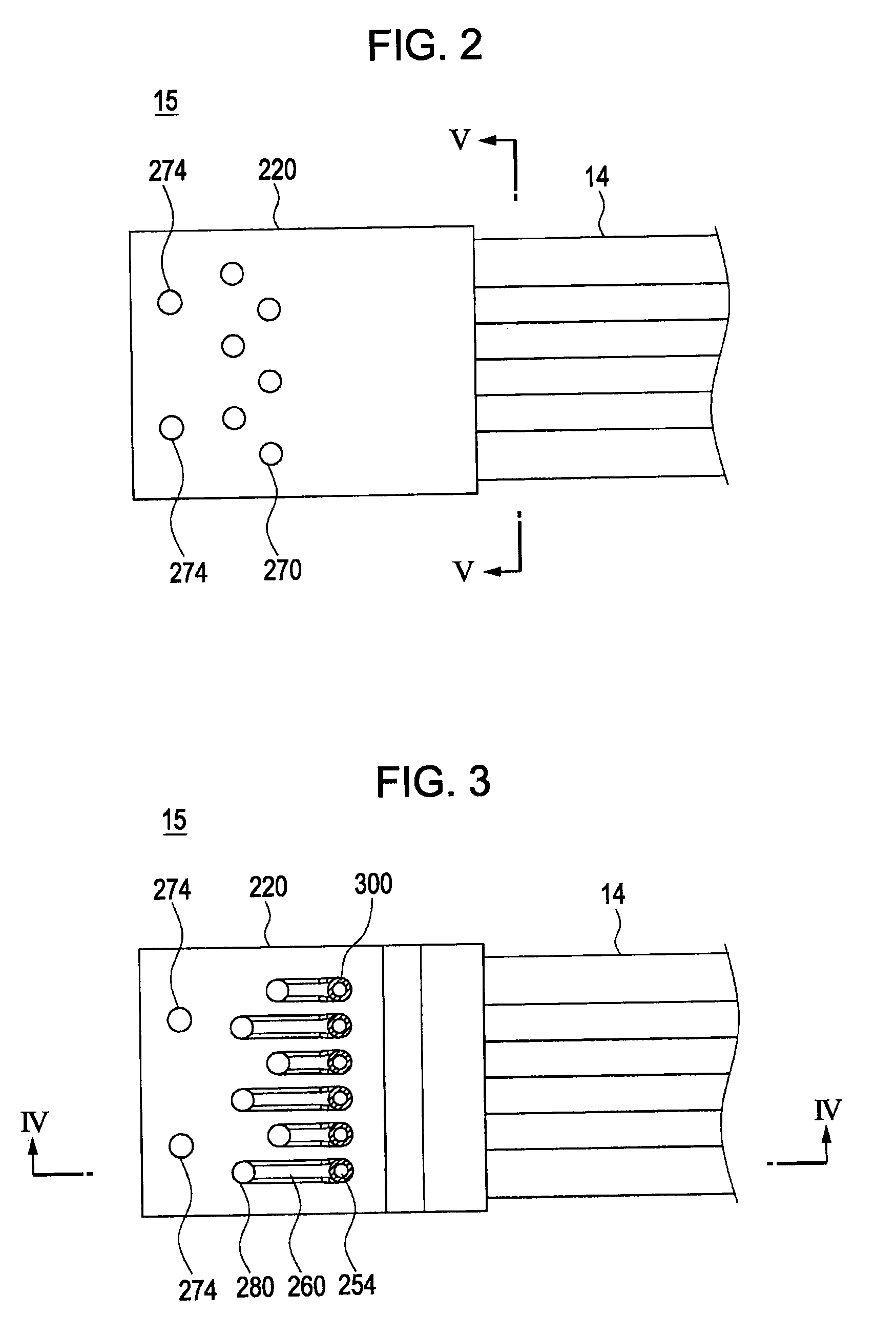
[0049]Although not shown in FIG. 3, the communication grooves 260 are sealed with a film 240 which is hermetically adhered to adhesive sections 242 of the molded body 220. Thus, the flow channels 141 in the elastic tube 14 can communicate with the communication ports 270 via the communication grooves 260 and the communication holes 280. Although stainless-steel tubes are used as the metallic cylindrical members 300 in the first embodiment, cylindrical members of other materials may be used alternatively as long as they have enough strength for maintaining their shape against pressure applied during the molding process of the connector 15.
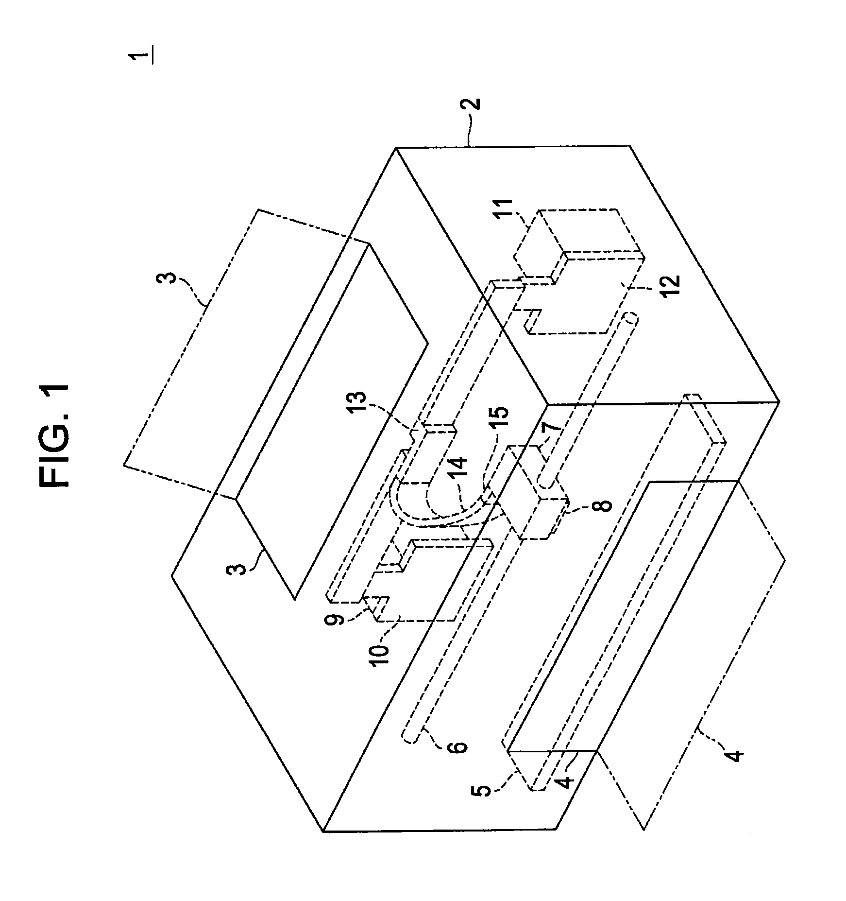
[0050]FIG. 5 is a cross-sectional view of the elastic tube 14 taken along line V-V in FIG. 2. As shown in the drawing, the elastic tube 14 has a multi-tube structure having the plurality of flow channels 141. The flow channels 141 are arranged in isolation from each other on a single plane and can individually allow fluids to flow therethrough. The ...
second embodiment
[0058]FIG. 7 is a cross-sectional view of a joint 510 according to the invention, which includes a male connector 512 and a female connector 514 that can be manufactured by the above-described forming method. As shown in the drawing, the male connector 512, which is shown at the right side of the drawing, and the female connector 514, which is shown at the left side of the drawing, form a pair so as to constitute the joint 510 between elastic tubes 14.
[0059]The male connector 512 has a first elastic tube 14 whose one end extends into a molded body 290 through one side surface thereof, and metallic cylindrical members 300 whose first ends extend into the first elastic tube 14. The second ends of the metallic cylindrical members 300 extend outward from the other side surface of the molded body 290. Each of the metallic cylindrical members 300 extending outward from the molded body 290 has an O-ring 310 fitted thereto.
[0060]On the other hand, the female connector 514 is similar to the ...
third embodiment
[0063]FIG. 8 is a cross-sectional view of a joint 520 according to the invention, which can be manufactured by the above-described forming method. As shown in the drawing, the joint 520 similarly includes a male connector 522, which is shown at the right side of the drawing, and a female connector 524, which is shown at the left side of the drawing. The male connector 522 and the female connector 524 form a pair so as to constitute the joint 520 between elastic tubes 14.
[0064]The male connector 522 has a first elastic tube 14 whose one end extends into a molded body 290 through one side surface thereof, and metallic cylindrical members 300 whose first ends extend into the first elastic tube 14. The second ends of the metallic cylindrical members 300 are flush with the other side surface of the molded body 290. Furthermore, the other side surface of the molded body 290 has grooves which surround the corresponding metallic cylindrical members 300 and have O-rings 310 fitted therein.
[0...
PUM
| Property | Measurement | Unit |
|---|---|---|
| Temperature | aaaaa | aaaaa |
| Diameter | aaaaa | aaaaa |
| Length | aaaaa | aaaaa |
Abstract
Description
Claims
Application Information