Mobile communication device with reduced electric field emission levels near the earpiece

a mobile communication and electric field technology, applied in the direction of antennas, antenna details, antenna earthings, etc., can solve the problems of increasing costs, reducing problems, and reducing transmission costs, so as to achieve the effect of reducing transmission costs

Active Publication Date: 2007-08-02
NOKIA TECHNOLOGLES OY
View PDF6 Cites 27 Cited by
  • Summary
  • Abstract
  • Description
  • Claims
  • Application Information

AI Technical Summary

Benefits of technology

[0007] According to the invention, there is provided a mobile communication device including a body, an earpiece and an antenna comprising: an antenna element; and a conductive ground element to cooperate with the antenna element, provided in the body and in use ha

Problems solved by technology

It is well known that electromagnetic radiation can interfere with the functions of electronic equipment such as computers, airplane equipment and medical equipment.
Hearing aids have been developed that are more immune to electromagnetic radiation than hitherto, but this has only alleviated the problem.
However, neck loops require users to buy additional electronic devices in order to be able to use the mobile phone, which increases costs, and shields are considered by many to have a detrimental effect on the attractiveness of the mobile phone.
Thus, the solution

Method used


Image

  • Mobile communication device with reduced electric field emission levels near the earpiece
  • Mobile communication device with reduced electric field emission levels near the earpiece
  • Mobile communication device with reduced electric field emission levels near the earpiece

Examples


Embodiment Construction

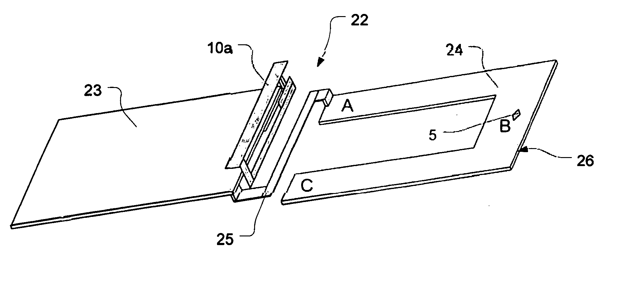
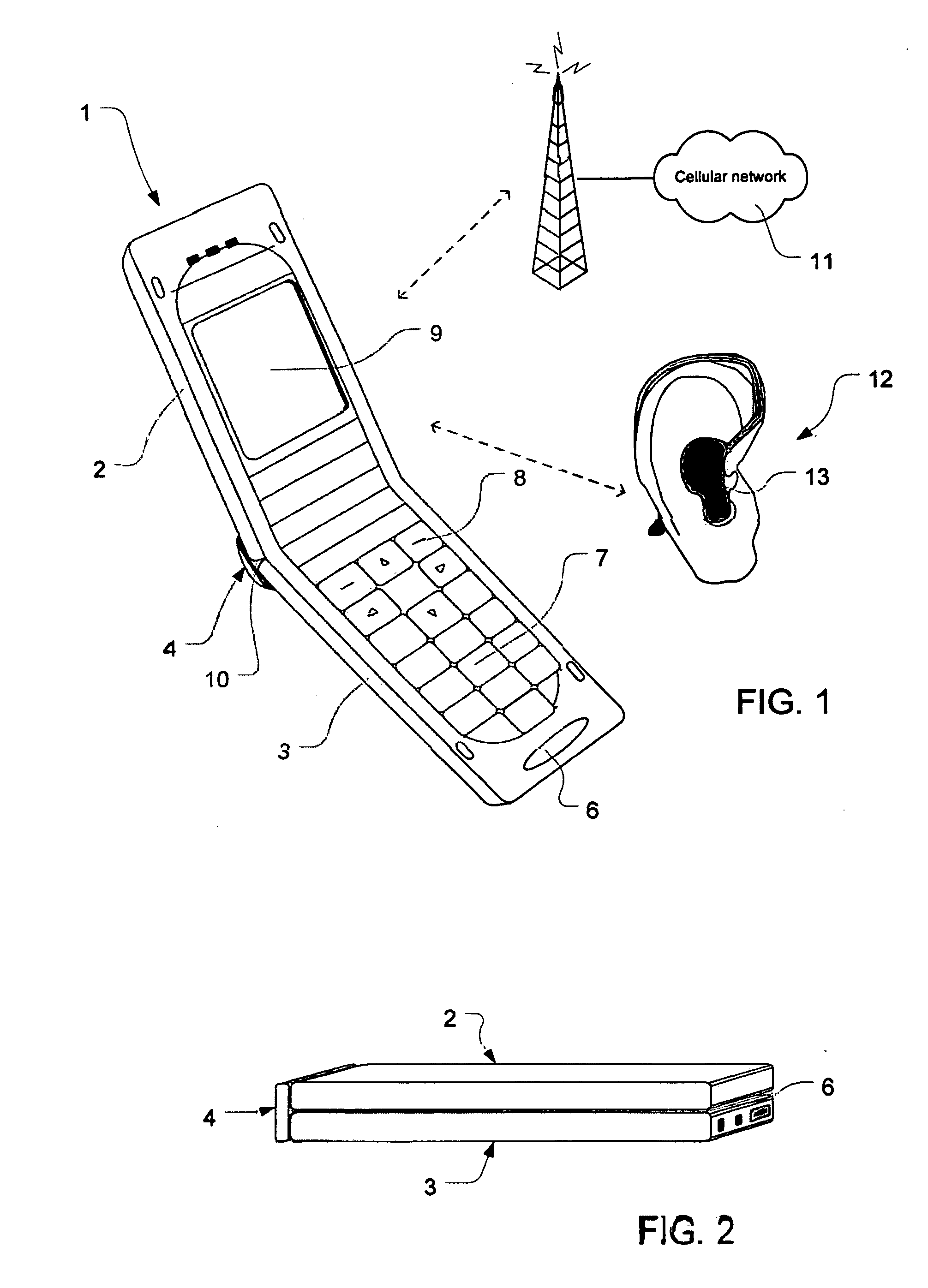
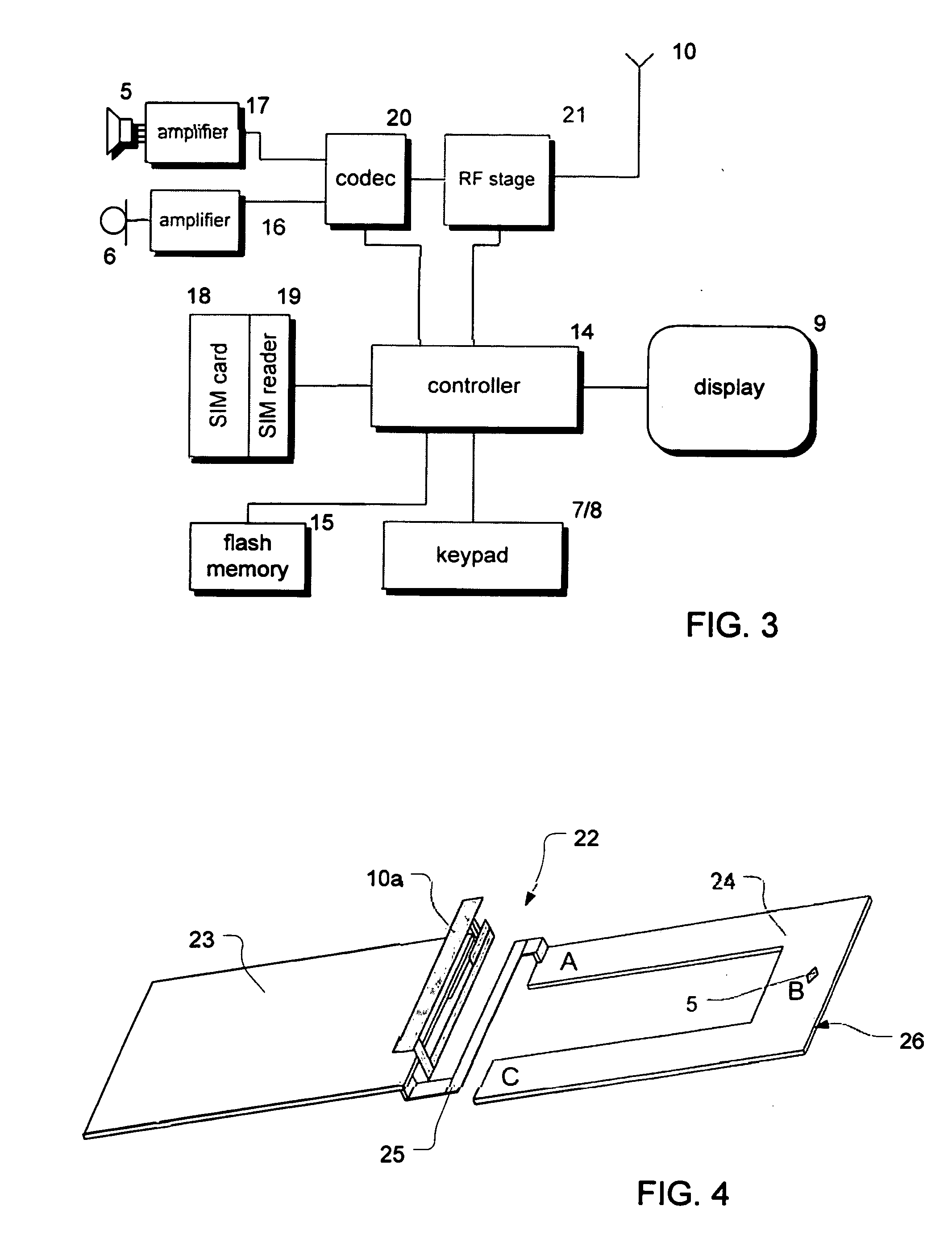
[0021] Referring to FIGS. 1 and 2, a mobile station in the form of a flip mobile telephone handset 1 includes a first hinged body part 2, a second hinged body part 3 and a linking body part 4 for housing a hinge between the first and second body parts. The handset further comprises an earpiece 5, a microphone 6, a keypad 7, with soft keys 8 which can be programmed to perform different functions, an LCD display 9 and an internal antenna 10 including an element located in the linking body part. The earpiece is located in the first hinged body part 2 and the microphone is located in the second hinged body part 3.

[0022] The handset is operable to communicate through cellular radio links with one or more individual public land mobile networks (PLMNs) 11 based on technologies including but not limited to the TDMA and CDMA technologies.

[0023] In FIG. 1 the handset 1 is open, whereas in FIG. 2 the handset is folded in its closed state. When a user makes a call using the handset, the hands...


PUM


Abstract

A mobile communication device (1) is provided with an antenna (10) having an antenna element (10a) and a conductive ground element (26) to cooperate with the antenna element. In use, RF currents are generated in the conductive ground element and as a result an oscillating electric field arises. The conductive ground element is arranged in the device (1) such that the point of highest electric field is located away from the region where the earpiece (5) is positioned in order to reduce the emission of the electric field to the ear (12). The conductive ground element (26) may be provided in a conductive layer of the Printed Circuit/Wire Board (24) of the device. The point of highest electric field in a in a conductive layer arises at the end of the physical path near a physical end of the layer, which in a conventional flip-phone typically corresponds to the top of the first hinged body part (2) where the earpiece (5) is also positioned. According to the invention, the layer is serpentine shaped and arranged such that the end of the electrical path of the Printed Circuit/Wire Board is located approximately half a wavelength of the oscillating field away from the area of the earpiece. Alternatively, tracks or wires (27, 28) acting as ground extensions may be connected to the ground plane (26) to move the end of the electrical path and the high electric field away from the region of the earpiece.

Description

FIELD OF THE INVENTION [0001] The invention relates to a mobile communication device with a reduced electric field in the vicinity of its earpiece. More particularly, the invention relates to a mobile communication device which is compatible with hearing aids. BACKGROUND [0002] It is well known that electromagnetic radiation can interfere with the functions of electronic equipment such as computers, airplane equipment and medical equipment. By their very nature, mobile phones provide a source of electromagnetic radiation and in many situations it is desirable that mobile phones be used in the vicinity of other electronic equipment without producing interference. For example, it is necessary for a wearer of a hearing aid that the radiation from a mobile phone does not interfere with the hearing aid to such an extent that the audio signals from the mobile phone earpiece cannot be heard by the wearer of the hearing aid. The introduction of digital wireless technologies has further wors...

Claims


Application Information

Patent Timeline
IPC IPC(8): H01Q1/24
CPCH01Q1/243H04B1/3838H01Q9/285H01Q1/245
Inventor HAHO, MIKKORINTAMAKI, ASKOKENTTALA, JARMOAUTTI, MARKO
Owner NOKIA TECHNOLOGLES OY
Why Eureka
Try Eureka