[0013]The power source frame is non-conductive and has a cavity adopted to house the power source. The power source frame can also have a receptacle for receiving and housing a connector end of the
light source. The power source frame therefore serves as a fitted compartment for holding in place and protecting the various internal components of the flashlight. The power source frame provides significant protection to the power source and the
light source and serves to
cushion these elements from the adverse affects of any shock the flashlight might receive from normal
wear and tear or inadvertent mishaps. The power source frame housing encases the power source frame, and provides further protection to the internal components of the flashlight, in addition to that provided by the power source frame. The power source frame housing thus serves to provide an additional level of protection to the light source and the power source and enhances the durability of the flashlight.
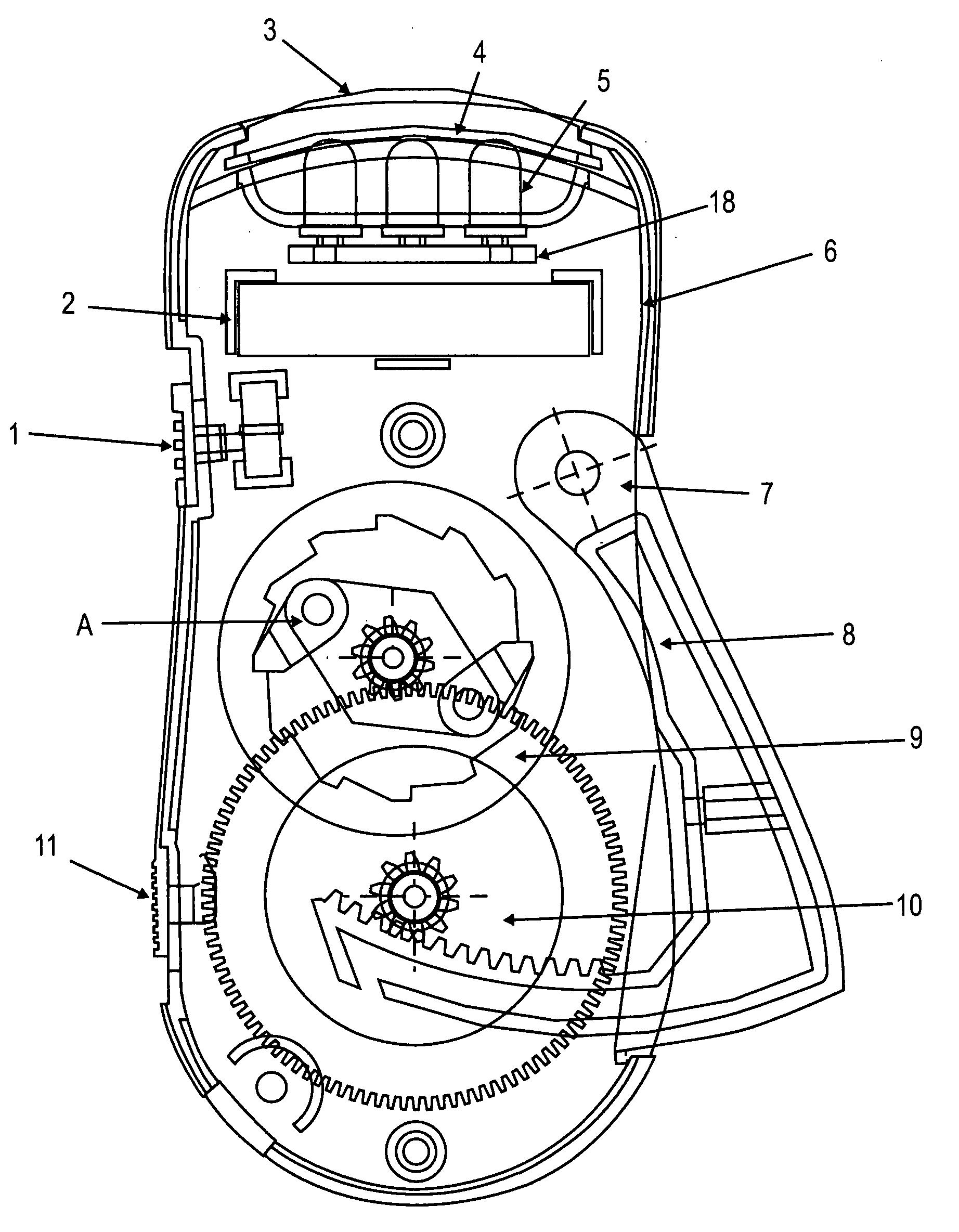
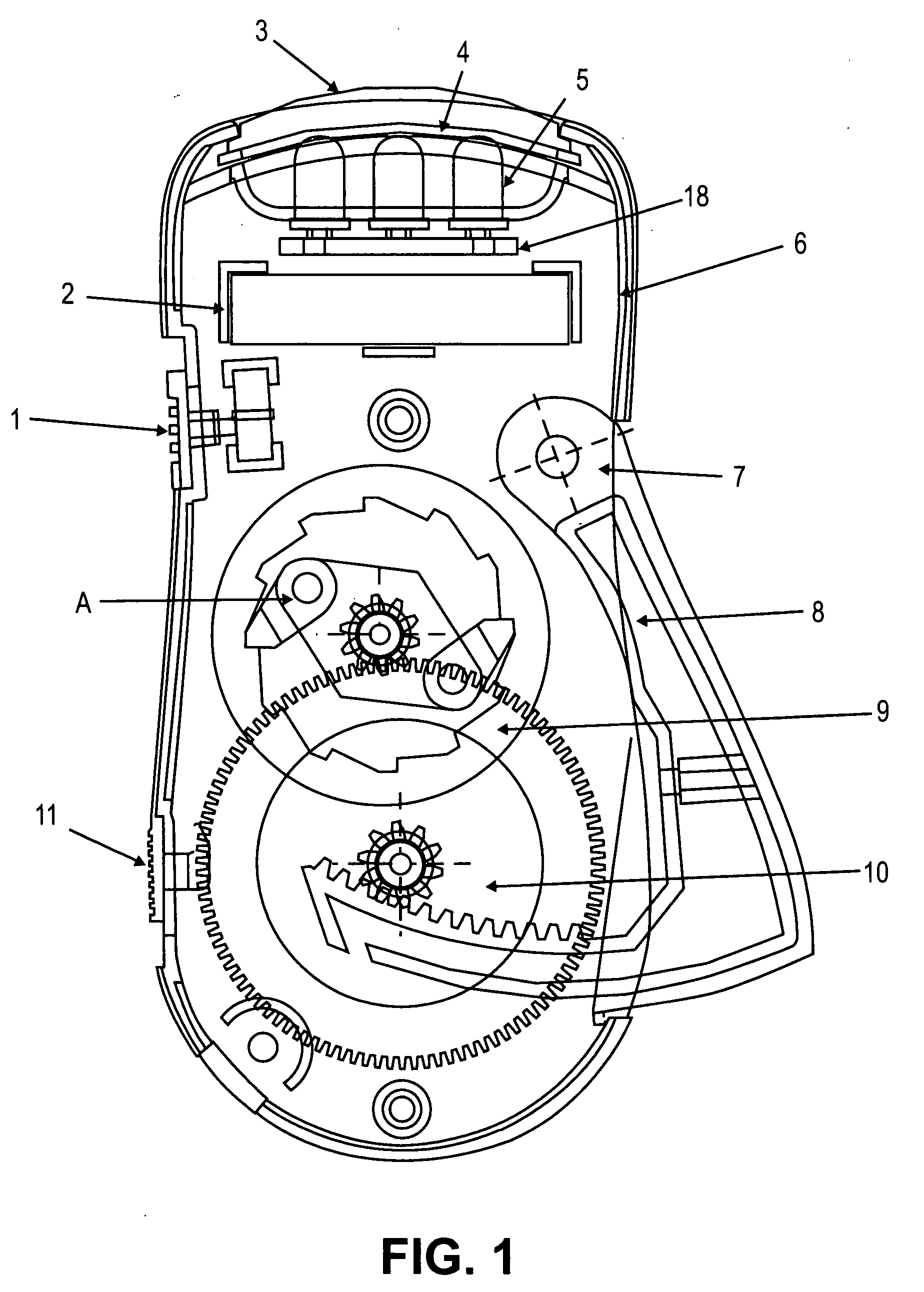
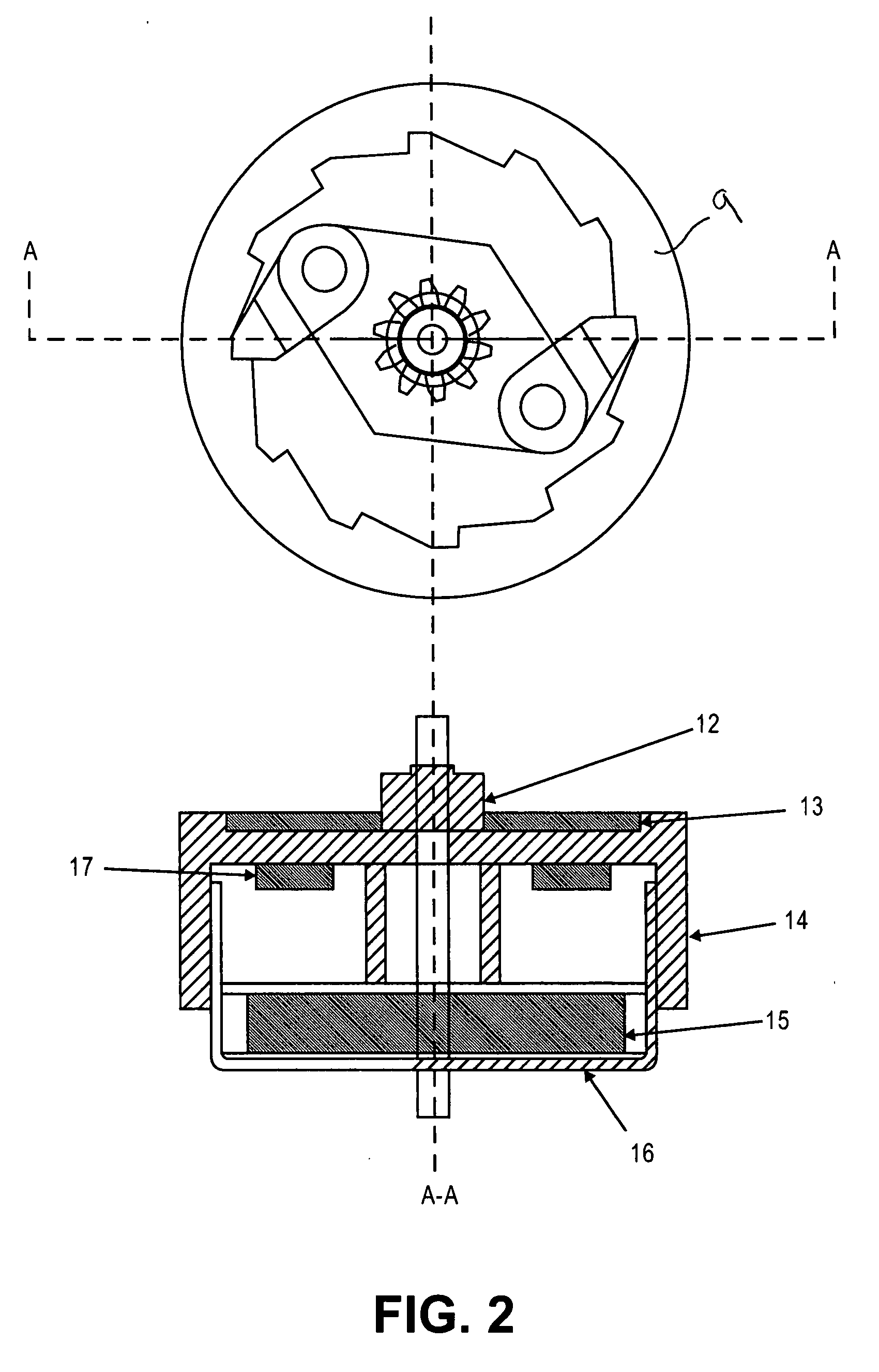
[0017]The spring loaded retractable
handle, when released by the slide switch and hand pumped three or four times immediately activates a series of gears to drive a
dynamo. The three or four pumps on the retractable
handle causes the dynamo to spin at or slightly 1650 RPM producing 3.0 dc volts and adequate current that recharges the Ni-MH,
Nickel Cadmium, or
Lithium Rechargeable battery, thereby creating additional
operating time. One-handed charging with the squeeze of the retractable lever, allows for users to operate the light with one hand free for other tasks (e.g., manipulating others objects, holding a stair railing, opening a
car door, turning a page in a book, etc).
[0018]Another unique feature is that the squeezing of the spring loaded, retractable lever allows the user to rest between pumping actions (while the lever springs back into open position), thereby reducing the likelihood of operator fatigue. This retractable hand generator when combined with the rechargeable NiMH,
Nickel-
Cadmium, or
Lithium technology allows for ease of operation during recharging. Finally, another unique and distinguishing feature of this invention is that the user is able to actually use the flashlight during the recharging process, and as aforementioned, have one hand free throughout the entire process.
[0019]This invention allows a user to meet both of these conditions simultaneously when the light emitted from the unit is in a state of failure: (1) allows recharging with squeezing of the spring-loaded retractable handle (which is obviously not possible with non-rechargeable units), and continued use of the unit because it is producing light on whatever the user wishes to aim focus upon with the flashlight allowing to be aimed in a stable manner and; (2) to conduct this recharging process with the use of only one hand. Consequently, another unique aspect of this invention is that it is ideal during emergency outages because users are never in the dark and can aim and focus the LEDS even during the recharging stage with one hand. In certain emergencies, having a hand free (even during recharging) is important; an example of this would be the application for a miner who might be trapped in a collapsed mine.
[0020]It is also important to note that the retractable, spring-loaded recharging lever (when not in use, i.e., in the retrained position) stores conveniently within the housing of the flashlight, which is unique in the flashlight industry. The retractable handle guarantees that the flashlight is not intrusive in size allowing for more efficient portability. When retracted, this handle used for recharging the internal battery in the flashlight allows for the flashlight to remain small in size and easy to transport. In summary, the spring-loaded slide switch, which can lock in place when the owner desires to hide the handle or can be released, serving as the means to recharge the battery, is the first spring loaded, retractable handle in the flashlight industry.
[0021]Furthermore, when the spring loaded handle is in the restrained position it provides additional protection to the multiple
gear train assembly and the dynamo. Finally, there is an obvious
advantage to this mechanism, in terms of portability and storage, i.e., there are no protruding or bulky components that make it difficult for users to transport in their pockets or purses, or store in a glove compartment.

