
High-accuracy sliding bearing

a high-accuracy, bearing technology, applied in the direction of bearings, shafts and bearings, rotary bearings, etc., can solve the problems of metal contact, deterioration of rotational accuracy, and wrapping of sliding bearings around shafts, so as to achieve high-accuracy sliding bearings, high productivity, and high accuracy

Inactive Publication Date: 2007-08-02
NTN CORP +1
View PDF10 Cites 23 Cited by
  • Summary
  • Abstract
  • Description
  • Claims
  • Application Information

AI Technical Summary

Benefits of technology

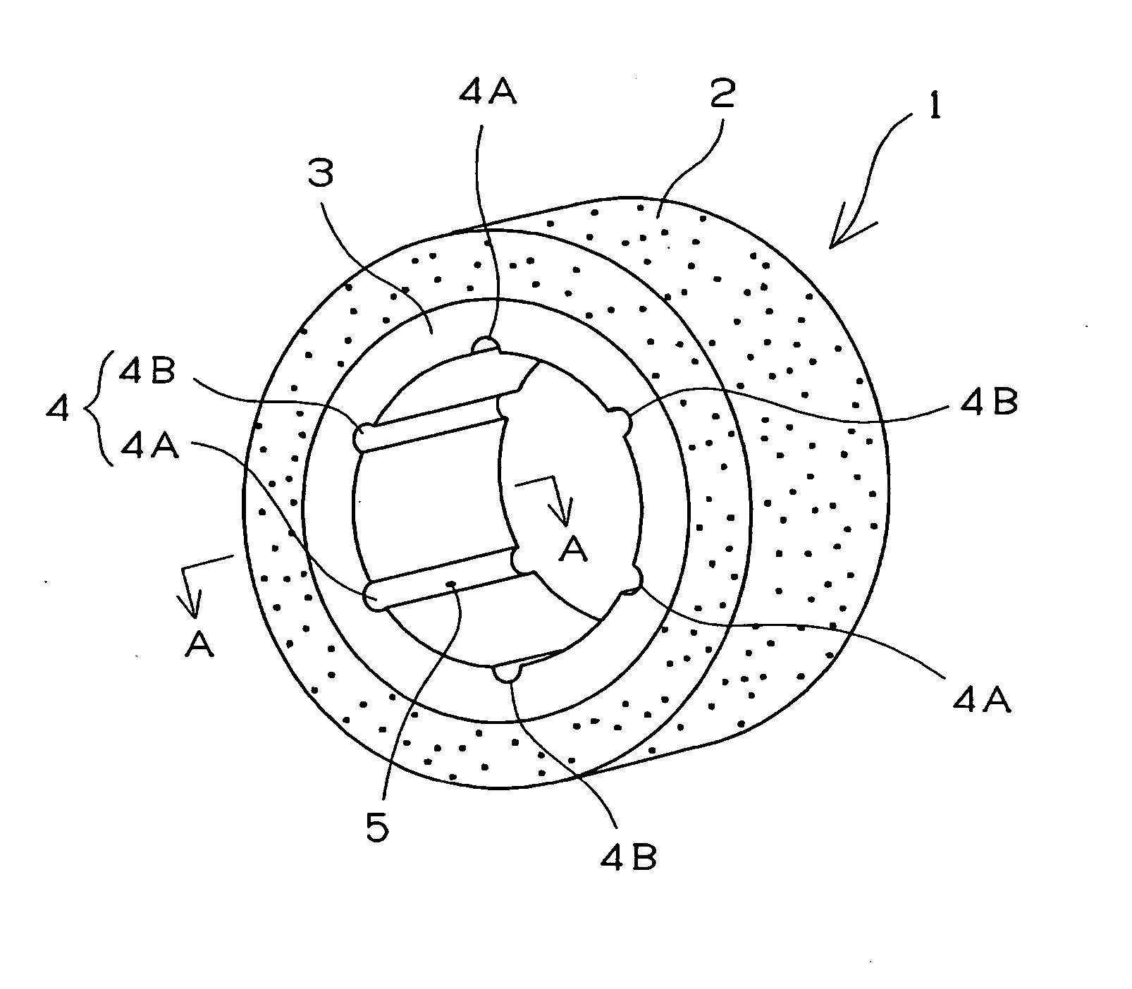
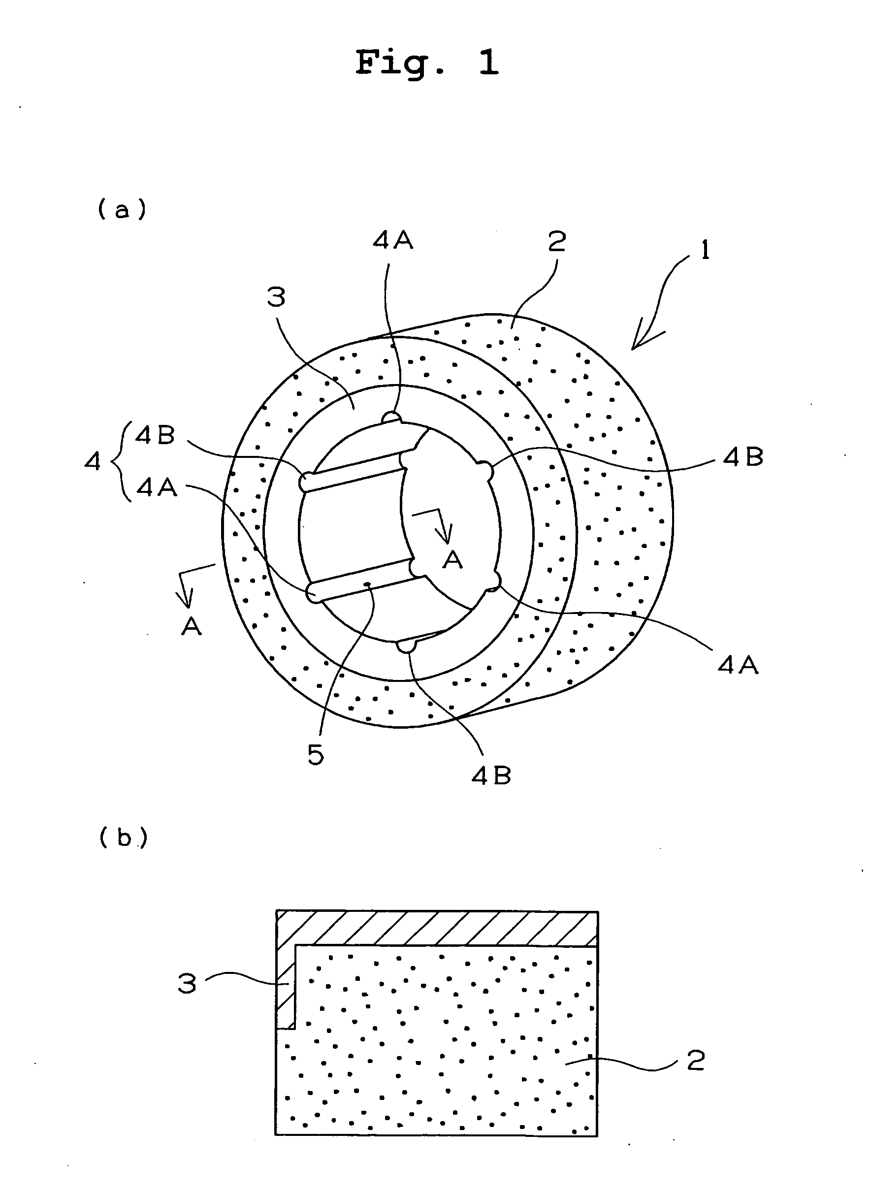
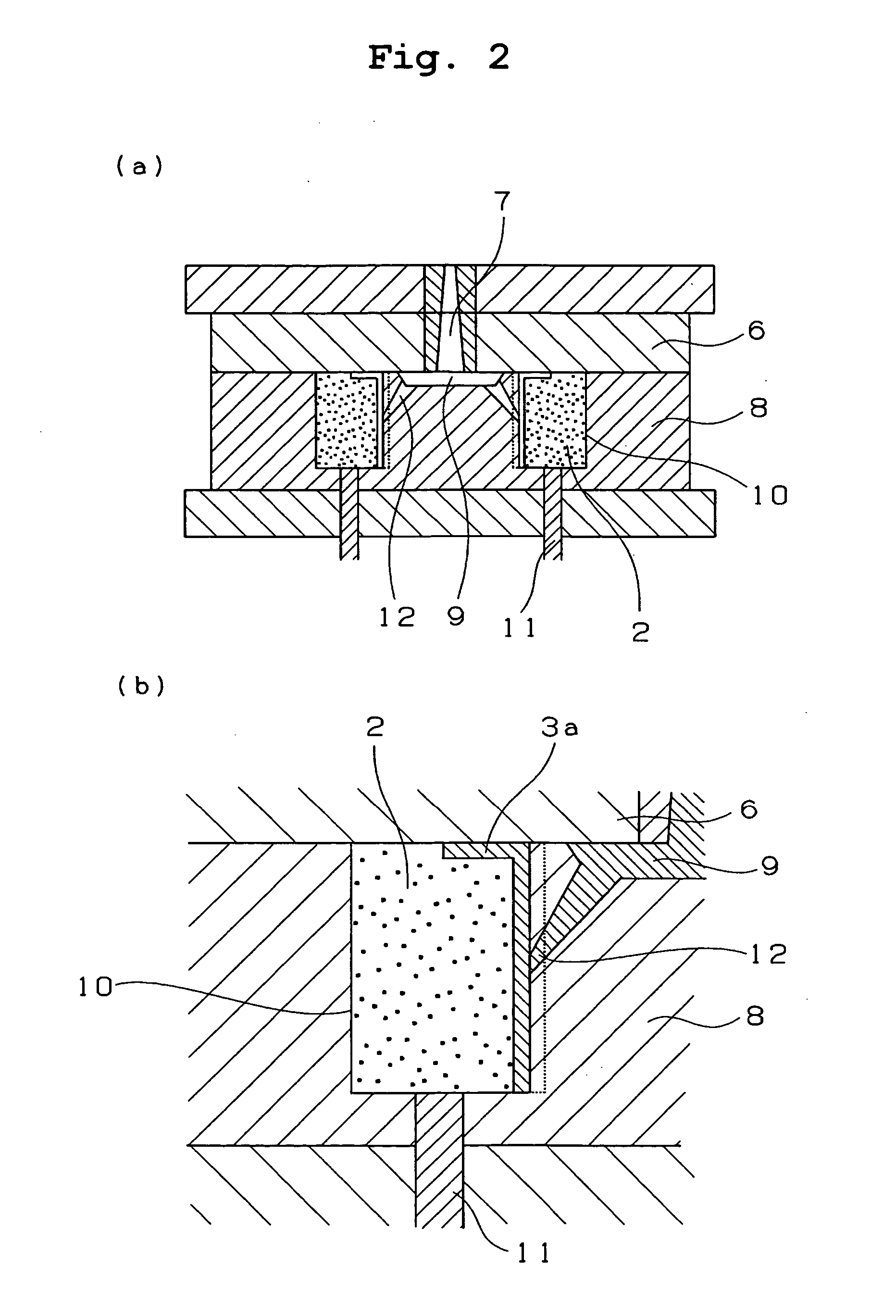
[0016] In the high-accuracy sliding bearing of the present invention, the resin layer is molded through the tunnel gates. Therefore it is unnecessary to treat the gate mark and thus the high-accuracy sliding bearing can be produced with a high productivity. Particularly each of the tunnel gates is disposed on the bottom of each of a plurality of the grooves formed on the bearing sliding surface. Particularly each of the tunnel gates is disposed on the bottom of each of a plurality of the grooves formed on the radial sliding surface of the cylindrical bearing or the thrust sliding surface thereof. Accordingly the gate mark does not remain on the sliding surface. Further abraded powder generated by sliding escapes to the grooves and does not remain on the sliding surface. Consequently the sliding bearing having a high accuracy is produced.

Problems solved by technology

But there is a fear that the sliding bearing composed of the porous sintered metal impregnated with the oil wears the mating material made of a soft material.
Further when the supply of the lubricating oil is interrupted, there is a fear that metal contact occurs.
But in this case, a problem that owing to contraction and expansion of the resin material, wrap of the sliding bearing around the shaft occurs.
Thereby a problem that the rotational accuracy deteriorates occurs.
But as the accuracy of the high-accuracy sliding bearing becomes higher, a gate mark formed at a time of injection molding may adversely affect the performance of the bearing.
Thus the high-accuracy sliding bearing may have an inferior productivity.

Method used


Image

  • High-accuracy sliding bearing
  • High-accuracy sliding bearing
  • High-accuracy sliding bearing

Examples


example

[0074] A bearing peripheral part consisting of a sintered metal (coefficient of linear thermal expansion: 1.1×10⁻⁵ / ° C.) containing not less than 90% of Fe having a dimension of φ8.5 mm×φ14 mm×t 5 mm was prepared. The bearing peripheral part was inserted into a die for injection molding use. A resin material shown below was molded on the inner-diameter surface of the bearing peripheral part through tunnel gates by carrying out a method described below. A composite sliding bearing having a dimension of φ8 mm×14 mm×t 5 mm was prepared. The composite sliding bearing had three axial grooves each having a gate mark formed thereon and three axial grooves not having the gate mark formed thereon, with the six grooves disposed at regular intervals and with the three axial grooves each having the gate mark formed thereon alternating with the three axial grooves not having the gate mark formed thereon (configuration: FIG. 1(a) , thickness of resin layer: 250 μm). A test was conducted on the pr...


PUM

PropertyMeasurementUnit
Thicknessaaaaaaaaaa
Distanceaaaaaaaaaa
Coefficient of linear thermal expansionaaaaaaaaaa

Abstract

The present invention provides a high-accuracy sliding bearing which eliminates the need for treating a gate mark, has a high accuracy, is excellent in its mechanical strength, and is in its productivity. A sintered metal (2) is used as a bearing peripheral part. A resin material is molded at a sliding portion of the bearing peripheral part to form a resin layer (3). In the resin layer (3), a product of a coefficient of linear thermal expansion of the resin material and a thickness of the resin layer is not more than 0.15. The resin layer (3) is molded through tunnel gates. The resin layer comprises a plurality of axial grooves (4A) and (4B) on a bearing sliding surface thereof, and the tunnel gate marks (5) are alternately formed on a bottom of each of the grooves.

Description

TECHNICAL FIELD [0001] The present invention relates to a high-accuracy sliding bearing. BACKGROUND ART [0002] Conventionally, as a sliding bearing having a high rotational accuracy, a sliding bearing composed of a porous sintered metal impregnated with oil is known. When this sliding bearing is used by impregnating a porous material consisting of the sintered metal with the oil, it is possible to successively supplying a sliding interface with the oil. Thus it is possible to reduce a frictional force. Because a mating material of the sliding bearing is generally made of the same metal material as that of the sliding bearing, there is no fear of wrap of the sliding bearing around the mating material and separation of the sliding bearing therefrom owing to the difference between the linear expansion degree of the mating material and that of the sliding bearing. Because the processing accuracy of this metal material can be enhanced, the metal material is suitably used at a position wh...

Claims


Application Information

Patent Timeline
IPC IPC(8): F16C33/02B29C45/14B29C45/27F16C17/02F16C17/04F16C17/10F16C33/10F16C33/20
CPCB29C45/14622B29C45/2708B29K2705/00F16C33/201F16C17/10F16C33/1065F16C17/02
Inventor EGAMI, MASAKISHIMIZU, SEIJITANIMARU, TAKESHI
Owner NTN CORP
Learn More