Silicon-containing steel composition with improved heat exchanger corrosion and fouling resistance

Inactive Publication Date: 2007-08-02
EXXON RES & ENG CO
View PDF46 Cites 14 Cited by
  • Summary
  • Abstract
  • Description
  • Claims
  • Application Information

AI Technical Summary

Benefits of technology

[0056] The insert 50 is relevant to fouling beyond the petroleum and petrochemical industries. Other potential applications include for example, black liquor fouling and paper slurry pipe systems in the paper and pulp industry, microbiological contamination (bio-fouling) in the water treatment and distillation industry, product contamination in the pharmaceutical and semiconductor industries, reduction of contamination pick-up and increasing the effectiveness of conventional decontamination techniques for recirculation piping in the nuclear power industry and piping and exchangers used in the food, dairy and beverage industries where product build-up is a problem. Polymer sheeting in chemical reactor piping and heat exchangers used to produce polymers could also benefit as well as heat exchangers used to remove water during crystallization processes. There are many other examples of heat exchanger and piping fouling that can be ameliorated by this invention.
[0057] Many potential metal types can be used to form the insert and the metal chosen will depend on the nature of the fluid stream and the type of fouling that is being prevented. Though austenitic stainless steels such as types 304 and 316 can be used to fabricate the tube inserts, other stainless steel alloys could also be used, such as martensitic stainless steels such as type 410, ferritic stainless steels such as type 430. Other high performance alloys could also be considered such as superaustenitic stainless steels such as AL-6XN, duplex steels such as alloy 2205 and superferritic grades. Nickel based alloys will also be useful in certain environments and include the Ni—Cu, Ni—Cr—Fe, and Ni—Cr—Mo—Fe families of alloys. Cobalt and titanium alloys are also possible as well as pure metal inserts. Any metal or alloy that can be electropolished or otherwise smoothed is a possible material for use as an insert. The metals described herein are not limited to use with the insert; rather, it is contemplated that the materials may be used to form at least a portion of the heat transfer component.
[0058] Electropolishing or other means of reducing the surface roughness, as described above, may be used either before or after the tube with the insert is installed in the heat exchanger bundle to obtain the desired surface roughness. In some instances, it might be most advantageous to install the inserts into tubes that are already themselves installed within a heat exchanger and then electropolish the inserts. In other cases, it might be preferred to produce a stockpile of heat exchanger tubes with installed inserts and electropolish these before they are rolled into the tubesheets. The

Problems solved by technology

To further reduce and/or limit fouling, the heat transfer component may be subject to a vibrational for

Method used


Image

  • Silicon-containing steel composition with improved heat exchanger corrosion and fouling resistance
  • Silicon-containing steel composition with improved heat exchanger corrosion and fouling resistance
  • Silicon-containing steel composition with improved heat exchanger corrosion and fouling resistance

Examples


example 1

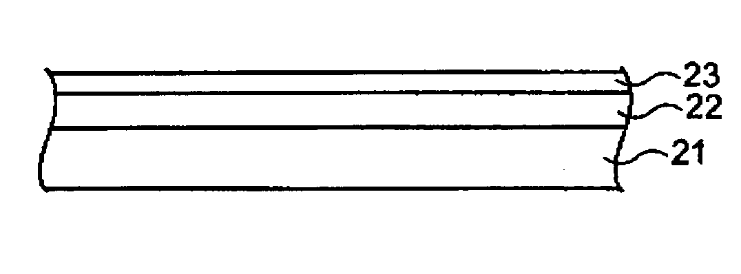
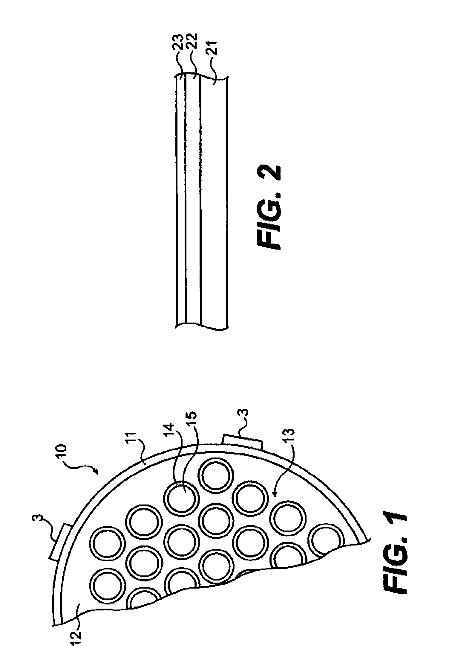
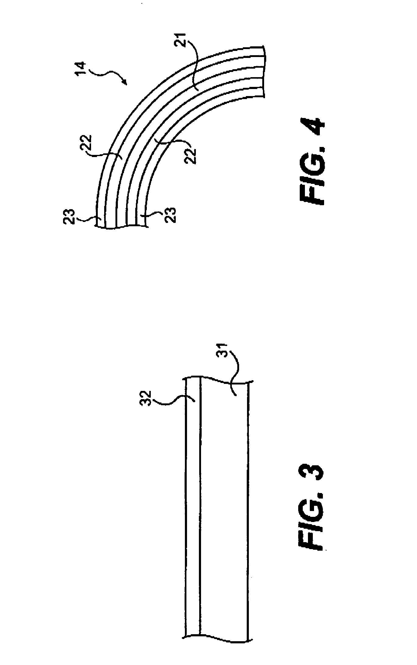
[0081] Silicon-containing steels listed in above table are prepared by arc melting. The arc melted steels are hot rolled into thick sheets of about ½ inch thickness. The sheets are annealed at 1100° C. overnight in inert argon atmosphere and furnace-cooled to room temperature. Rectangular samples of 0.5 inch×0.25 inch are cut from the sheets. The sample faces are polished to either 600 grit finish or Linde B (0.05 μm alumina powder) finish and cleaned in acetone. The sample is exposed to 60:40 vol. % of a crude mix (e.g. 60 vol. % Maya and 40 vol. % Olmeca crude mix) at 400° C. for 4 hours in a tubing bomb test apparatus. After testing, the specimen is cleaned in toluene and acetone sequentially and characterized by selected analytical instruments.

[0082] Both surface and cross sectional images of the tested specimen are examined using a Scanning Electron Microscopy (SEM). The atomic percent of elements in the silicon-containing steel composition is determined by standard Auger Elec...

example 2

[0083] The commercially available ALCOR Hot Liquid Process Simulator (HLPS) is used to evaluate the relative fouling potentials of the crude oils or blends described in the examples below. The test unit procedure designed for this testing is as follows.

[0084] In accordance with standard ALCOR HLPS test procedure, ALCOR runs are carried out by charging the one-liter reservoir with a crude oil or blend, heating the liquid (up to 150° C.) and pumping it across a vertically positioned, carbon-steel rod with a flow rate of 3.0 mL / minute. The spent oil is collected in the top section of the ALCOR reservoir, which is separated from the untreated oil by a sealed piston, thereby allowing for once-through operation. The system is pressurized with nitrogen (400-500 psig) prior to each test run to ensure gases remain dissolved in the oil during the test. The rod is electrically heated to a preset temperatures and held constant throughout the run. The rod surface temperature used for these test...


PUM

PropertyMeasurementUnit
Temperatureaaaaaaaaaa

Abstract

A heat transfer component that is resistant to both corrosion and fouling is disclosed having a heat exchange surface formed from a silicon containing steel composition including an alloy and a non-metallic film formed on a surface of the alloy. The alloy is formed from the composition η, θ, and ι, in which η is a metal selected from the group consisting of Fe, Ni, Co, and mixtures thereof, θ is Si, and ι is at least one alloying element selected from the group consisting of Cr, Al, Mn, Ti, Zr, Hf, V, Nb, Ta, Mo, W, Sc, La, Y, Ce, Ru, Rh, Ir, Pd, Pt, Cu, Ag, Au, Ga, Ge, As, In, Sn, Sb, Pb, B, C, N, P, 0, S and mixtures thereof. The non-metallic film comprises sulfide, oxide, carbide, nitride, oxysulfide, oxycarbide, oxynitride and mixtures thereof. The surface roughness of the heat transfer component is less than 40 micro inches.

Description

CROSS REFERENCE TO RELATED APPLICATIONZI [0001] This application relates to and claims priority to U.S. Provisional Patent Application No. 60 / 751,985, filed Dec. 21, 2005, entitled “Corrosion Resistant Material For Reduced Fouling, A Heat Exchanger Having Reduced Fouling And A Method For Reducing Heat Exchanger Fouling in a Refinery” and U.S. Provisional Patent Application No. 60 / 815,844, filed Jun. 23, 2006 entitled “A Method of Reducing Heat Exchanger Fouling in a Refinery” and U.S. Provisional Patent Application No. 60 / 872,493, filed Dec. 4, 2006 entitled “An Insert and Method For Reducing Fouling In A Process Stream,” the disclosures of which are hereby incorporated herein specifically by reference.FIELD OF THE INVENTION [0002] This invention relates to the reduction of sulfidation or sulfidic corrosion and the reduction of depositional fouling in general and in particular the reduction of sulifidation / sulfidic corrosion and the reduction of depositional fouling in heat transfer...

Claims


Application Information

Patent Timeline
IPC IPC(8): B32B15/04
CPCC10G9/203F28D7/16F28D2021/0059F28F19/00F28F19/002F28F19/02Y10T428/12549F28F21/082F28F25/08F28G7/00C10G2300/4075F28F21/083Y10T428/1259F28F19/06C22C38/00B32B15/012B32B15/011C23F15/00C22C38/18C22C38/02C22C38/22C22C38/04C22C38/60C22C38/50C22C38/44C22C38/48C22C38/38F28F13/10
Inventor CHUN, CHANGMINGREANEY, MARK A.BRUNO, THOMASCODY, IAN A.RAMANARAYANAN, TRIKUR A.CLAVENNA, LEROY R.
Owner EXXON RES & ENG CO
Why Eureka
Try Eureka