Welding process

a technology of arc welding and tuning parameters, which is applied in the direction of arc welding apparatus, welding apparatus, manufacturing tools, etc., can solve the problems of no procedure in the art which controls the arc welding process ad hoc, the process of electric arc welding is complicated, and the arc welding is a very complex science. achieve the effect of accurate tuning parameter values, low arc voltage and high arc voltag

Inactive Publication Date: 2007-08-09
ABB (SCHWEIZ) AG
View PDF13 Cites 26 Cited by
  • Summary
  • Abstract
  • Description
  • Claims
  • Application Information

AI Technical Summary

Benefits of technology

[0030] When the welding speed increases there is within the first phase a second behavior that comprises a plurality of droplets in the gap between the welding wire and the workpiece. In an instant moment the plurality of droplets will cause a direct contact between the welding wire and the workpiece. This will create a short cut of the electric system resulting in a low arc voltage. In another instant moment the total free gap between the droplets in the space between the wire and the workpiece will be short thus resulting in a somewhat higher arc voltage.
[0031] From the determined properties of the circuit one of the synergic lines is chosen for the process. From the chosen synergic line other process parameters such as wire feed rate, current and welding speed is determined. If any part of the electric circuit is exchanged or performing differently a new calibration is performed. The new calibration will produce new values for the input parameters in the simulation model. Thus the calibration will adopt the model to represent the new welding situation. The calibration of the model will results in performing very accurate tuning parameter values for the arc welding process.
[0032] The welding system also comprises computer means for performing the calibration and for controlling the welding process as well as memory means for storing synergic lines and other process data as well as programs carrying instruction for the computer means to carry out the calibration and the process control. The calibration and tuning procedure result in a time saving and a material saving. The method is applicable on any power source. When atomizing the calibration procedure the arc welding process will also be easy to use.

Problems solved by technology

Electric arc welding is a complicated process and the resulting deposition of molten metal into a weld pool for performing the welding operation is determined by a tremendous number of interrelated and non-interrelated parameters.
For this reason, arc welding is a very complex science.
There is no procedure in the art which controls an arc welding process ad hoc without the intervention of the welder or welding engineer.

Method used


Image

  • Welding process
  • Welding process
  • Welding process

Examples


Embodiment Construction

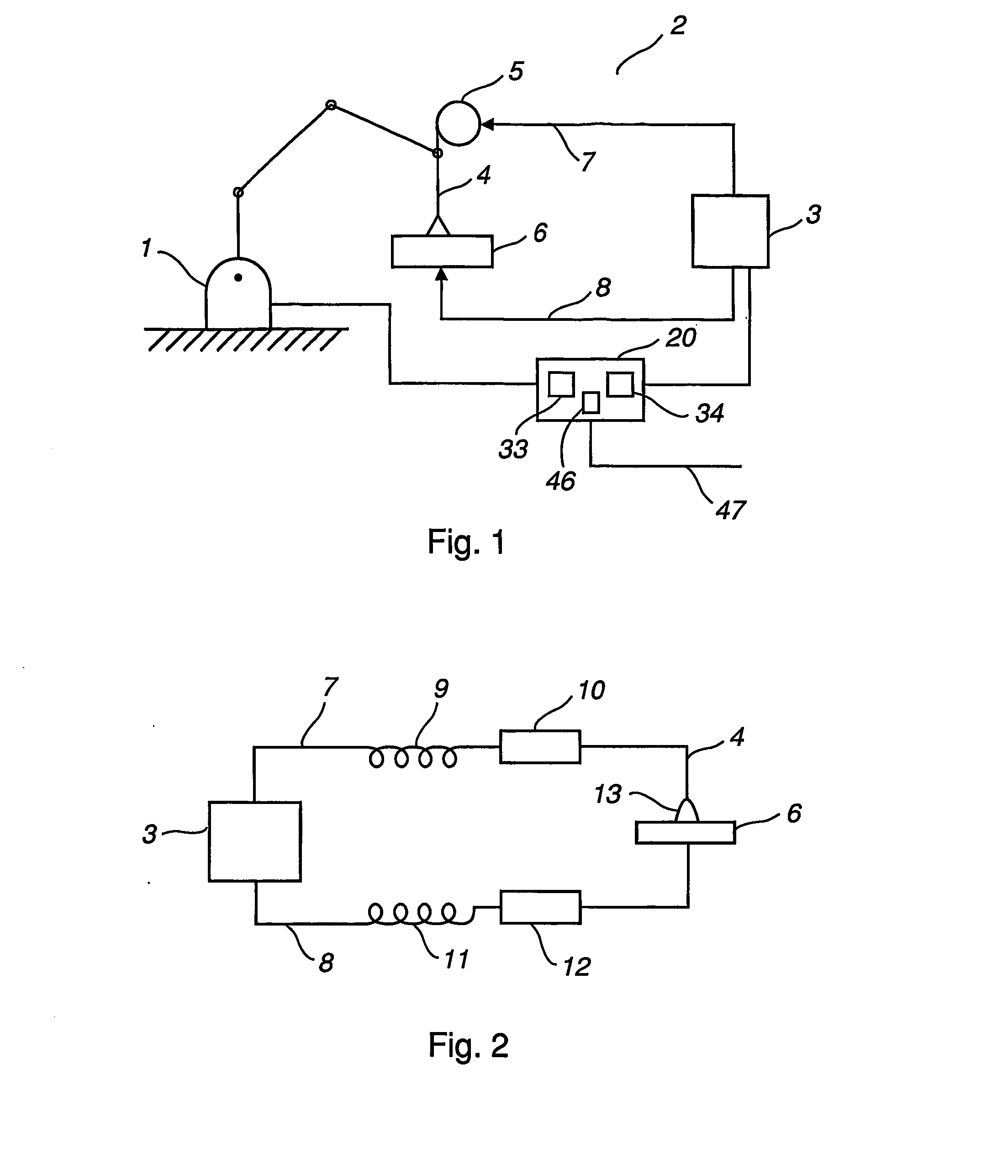
[0042] An arc welding system comprises according to FIG. 1 an industrial robot 1 and a electric circuit 2. The electric circuit comprise s a power source 3, a welding torch 4, a welding wire magazine 5 and a workpiece 6. The power source is connected to the torch with a first electric path 7. The power source is connected to the workpiece with a second path 8. When welding there is between the torch and the workpiece an arc 13. The arc welding system also comprises a control system 20 including processor means 33 and memory means 34 for storing data and a computer program. The control system comprises a simulation model of the arc welding system, means for tuning the welding system and input means (46) for receiving simulation model calibration parameter values. The control system also includes as shown in the figure a connection link (47) for data exchange and communication with another computer driven unit or a network, such as the Internet.

[0043] The electric circuit is shown in...


PUM

PropertyMeasurementUnit
voltageaaaaaaaaaa
resistancesaaaaaaaaaa
inductancesaaaaaaaaaa

Abstract

An arc welding system including an electric circuit including a power source, a welding torch with a consumable welding wire, a workpiece and a control system including a computer, memory and elements for tuning the arc welding system.

Description

TECHNICAL FIELD [0001] The present invention concerns a device and a method for tuning an arc welding system. More precisely the invention concerns a device and a method for tuning the arc welding system by using a simulation model of the arc welding process. In particular the invention concerns an arc welding system further including an industrial robot for holding and operating the welding torch. The invention also concerns a computer program product. BACKGROUND OF THE INVENTION [0002] In an arc welding process an electrical arc is established between a continuously fed consumable electrode and the base metal to be welded. Energy from the arc is used to melt the base metal and the electrode. Droplets form on the tip of the molten electrode and are transferred across the arc. An inert or slightly reactive shielding gas is provided in the arc region to reduce the reaction of the base metal, molten electrode, and arc due to contamination by the atmosphere. A power source is used to h...

Claims


Application Information

Patent Timeline
Patent Type & Authority Applications(United States)
IPC IPC(8): B23K9/10B23K9/095B23K9/173
CPCB23K9/1062B23K9/0953B23K9/173
Inventor KADDANI, AHMEDSMEDE, JANSKARIN, DICK
Owner ABB (SCHWEIZ) AG
Why Eureka
Try Eureka