Device and system for measuring forces

a technology of force measurement and device, applied in the field of measuring force, can solve the problems of electrical current needed for operating the electronic transducer, the electronic transducer is not free from drawbacks, and the electronic transducer is not free from drawbacks, and achieves the effects of low invasiveness, high numerical aperture, and high acceptable gap

Inactive Publication Date: 2007-08-09
IST SUPERIORE MARIO BOELLA +1
View PDF0 Cites 6 Cited by
  • Summary
  • Abstract
  • Description
  • Claims
  • Application Information

AI Technical Summary

Benefits of technology

[0007] In systems as described herein, forces, in particular, mechanical forces such as pressure or torque, may be measured and / or detected using the variations of light through an optical path caused by a force acting, either directly or indirectly, on said optical path. These systems make use of a variation in the photo-current detected at the output of an optical path with the link attenuation that is controlled by the force under test. Optical means adapted to be progressively inserted in an optical path as a result of the force under test, with the optical means being adapted to modify the transmission of optical signals through the optical path. The variation in the optical signals transmitted may then be used for obtaining indications relating to the force under test, such as, for instance, its intensity, direction or the like. This is, in particular, obtained by converting the variations in the optical signals transmitted through the optical path into a measure of current or voltage. Although this detection approach may be quite general in principle, it has been revealed to be reliable for the purpose of detecting and / or measuring forces, in particular, mechanical forces, such as, for example, pressure or torque. Moreover, when optical fibers are used for the purpose of defining an optical path, advantages arises in terms of costs, besides the advantages common to optical fibers such as light weight, minimal invasiveness, immunity to electromagnetic interferences and the impossibility of starting a fire or an explosion. Finally, if very high numerical aperture fibers, such as standard polymer optical fibers (POF) are used, advantages also arise due to the high acceptable gap between facing fibers, the less demanding mechanical tolerances and the possibility of using low cost sources and photodetectors.

Problems solved by technology

However, in spite of all the advantages cited above offered by electronic transducers, those electronic transducers are not free from drawbacks, especially when those electronic transducers are to be used for measuring mechanical forces, such as, for example, pressures and torques.
The most relevant drawback affecting electronic transducers arises from the fact that electrical current is needed for operating the electronic transducers.
However, the electrical current flowing through the electronic transducers may also be influenced by the external environment, thus rendering electronic transducers less reliable for applications in critical environments, such as in structures exposed to electrostatic discharges during thunderstorms or in electromagnetically noisy industrial premises.
Moreover, it may become difficult or risky to use electronic transducers in storage areas of highly flammable materials.
Finally, some types of electronic transducers are also not suitable for biomedical applications because the risk of electrocution may arise.

Method used


Image

  • Device and system for measuring forces
  • Device and system for measuring forces
  • Device and system for measuring forces

Examples


Embodiment Construction

[0036] While the present invention is described with reference to the embodiments as illustrated in the following detailed description as well as in the drawings, it should be understood that the following detailed description, as well as the drawings, are not intended to limit the present invention to the particular illustrative embodiments disclosed, but rather the described illustrative embodiments merely exemplify the various aspects of the present invention, the scope of which is defined by the appended claims.

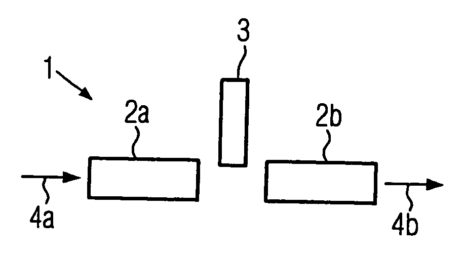
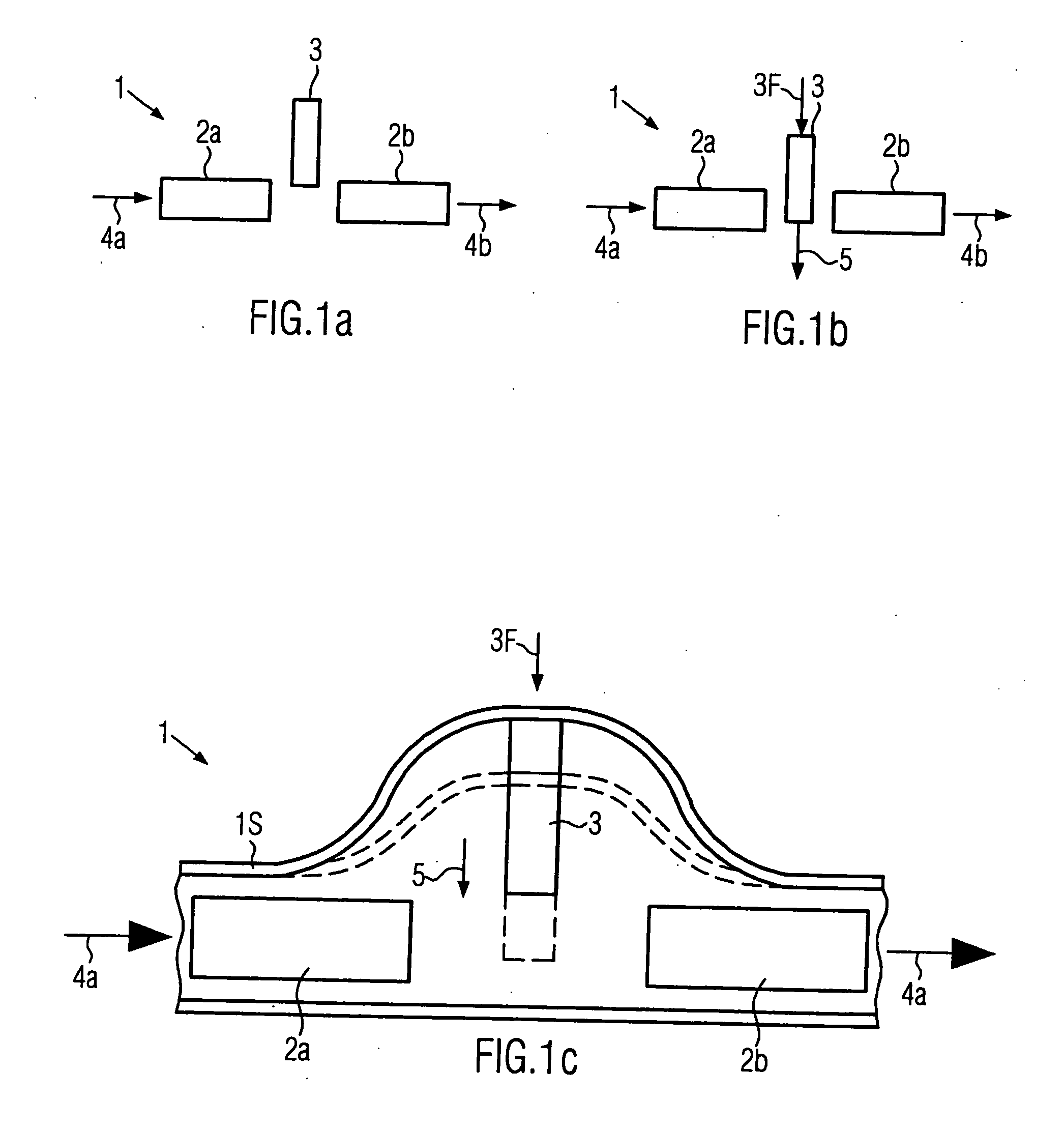
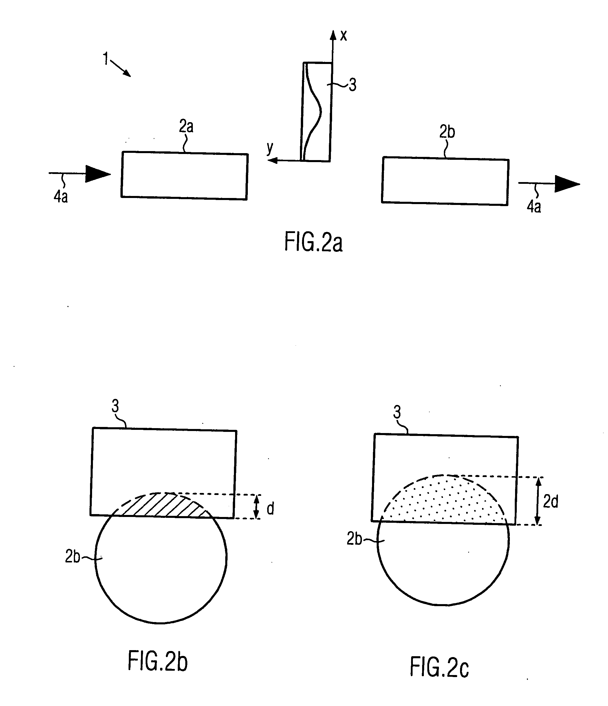
[0037] Transducers as described herein are understood to be of particular advantage when used for detecting and / or measuring transversal forces and rotational forces such as, for example, pressures and torques. For this reason, examples will be given in the following, in which corresponding embodiments of the optical transducers are used for detecting and / or measuring pressures and torques. However, it has to be noted that the use of the optical transducers is not limite...


PUM


Abstract

Optical transducers are provided for detecting forces such as, for example rotational and transversal forces acting on them, wherein, for the purpose of detecting said forces, optical signals are transmitted through an optical path defined by optical fibers. Moreover, optical means are provided, adapted to modify the transmission of the optical signals through the optical path, as a result of forces acting on them. The resulting optical signals exiting the transducer are then used for the purpose of detecting the forces acting on the transducer.

Description

[0001] This application claims the priority of European Patent Application No. 05016459.9, filed Jul. 28, 2005. BACKGROUND [0002] The present invention relates to the measurement of forces. In particular, the present invention relates to the measurement of mechanical forces, such as, for example, transversal forces (pressure) and rotational forces (torque). In more detail, the present invention relates to the measurement of forces by using optical transducers. [0003] During the last years, much development work has been devoted to the provision of devices adapted to measure and / or detect mechanical forces in a very reliable manner. Among the devices and systems developed and proposed, systems and devices based on very sophisticated electronic assemblies became the most largely used devices and systems. This, in particular, was due to the fact that the development in the sector of integrated circuits, and the corresponding reduction in size of circuits exploiting very complicated fun...

Claims


Application Information

Patent Timeline
Patent Type & Authority Applications(United States)
IPC IPC(8): G01J1/04G01J1/42
CPCG01L1/242
Inventor ABRATE, SILVIOPERRONE, GUIDO
Owner IST SUPERIORE MARIO BOELLA
Why Eureka
Try Eureka