Valve drive device, its control method and pump

a valve drive and control method technology, applied in the direction of piston pumps, diaphragm valves, engine diaphragms, etc., can solve the problems of variable elastic force unstable inability to achieve stable sealing property in the closing state of the valve element, so as to improve the reliability prevent the closing performance of the diaphragm valve. , the effect of improving th

Inactive Publication Date: 2007-08-09
SANKYO SEIKI MFG CO LTD
View PDF5 Cites 9 Cited by
  • Summary
  • Abstract
  • Description
  • Claims
  • Application Information

AI Technical Summary

Benefits of technology

[0012] In view of the problems described above, an embodiment of the present invention may advantageously provide a valve drive device in which its sealing property in a closing state of a valve element is stabilized and reliability regarding closing performance of the valve element can be improved, and provide a control method for the valve drive device and a pump utilizing the valve drive device.

Problems solved by technology

Therefore, since error of the motor and errors of respective members from a rotor to a valve element are accumulated or piled up, a stable sealing property in the closing state of the valve element is not obtained.
As a result, since closing performance of the valve element is varied, the sealing property in the closing state of the valve element is not stable.
Further, when the valve element is pressed with too strong force at the time when the flow path is closed, an elastic force of the valve element is varied due to hysteresis or the abutting part is worn.
As a result, the closing performance of the valve element is further varied and the sealing property in the closing state of the valve element becomes further more unstable.
As described above, in the conventional valve drive device, since the sealing property in the closing state of the valve element is hard to stabilize, reliability for closing performance of the valve element is not satisfactory.

Method used


Image

  • Valve drive device, its control method and pump
  • Valve drive device, its control method and pump
  • Valve drive device, its control method and pump

Examples


Embodiment Construction

[0048] A valve drive device in accordance with an embodiment of the present invention will be described below with reference to the accompanying drawings. The valve drive device described below can be mounted on a pump having an inflow path, a plurality of outflow paths, a pump chamber and a pump mechanism.

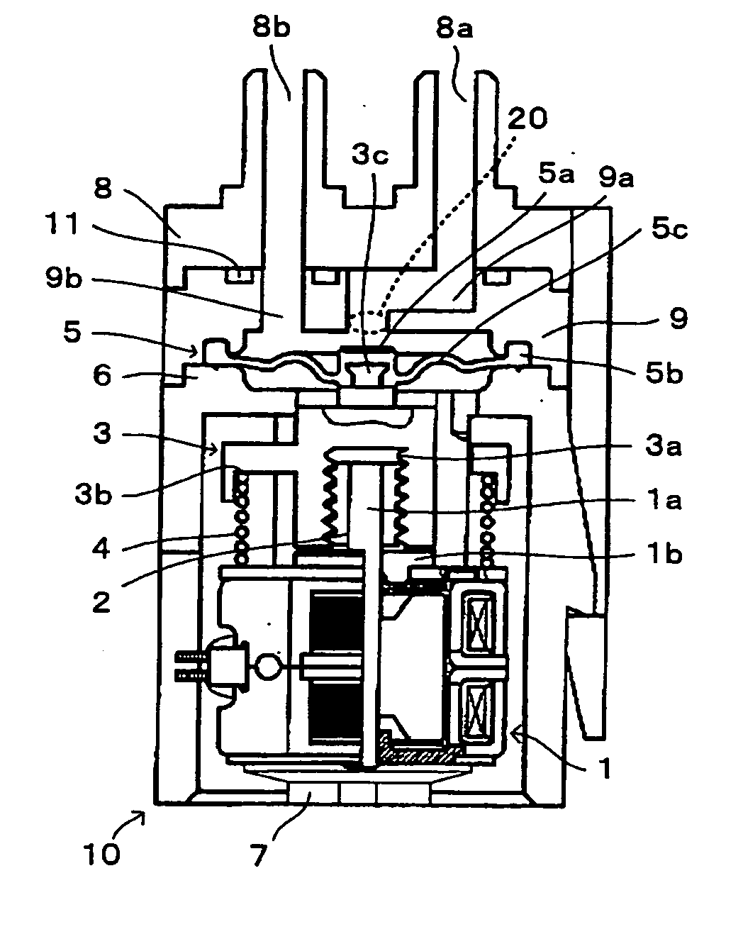
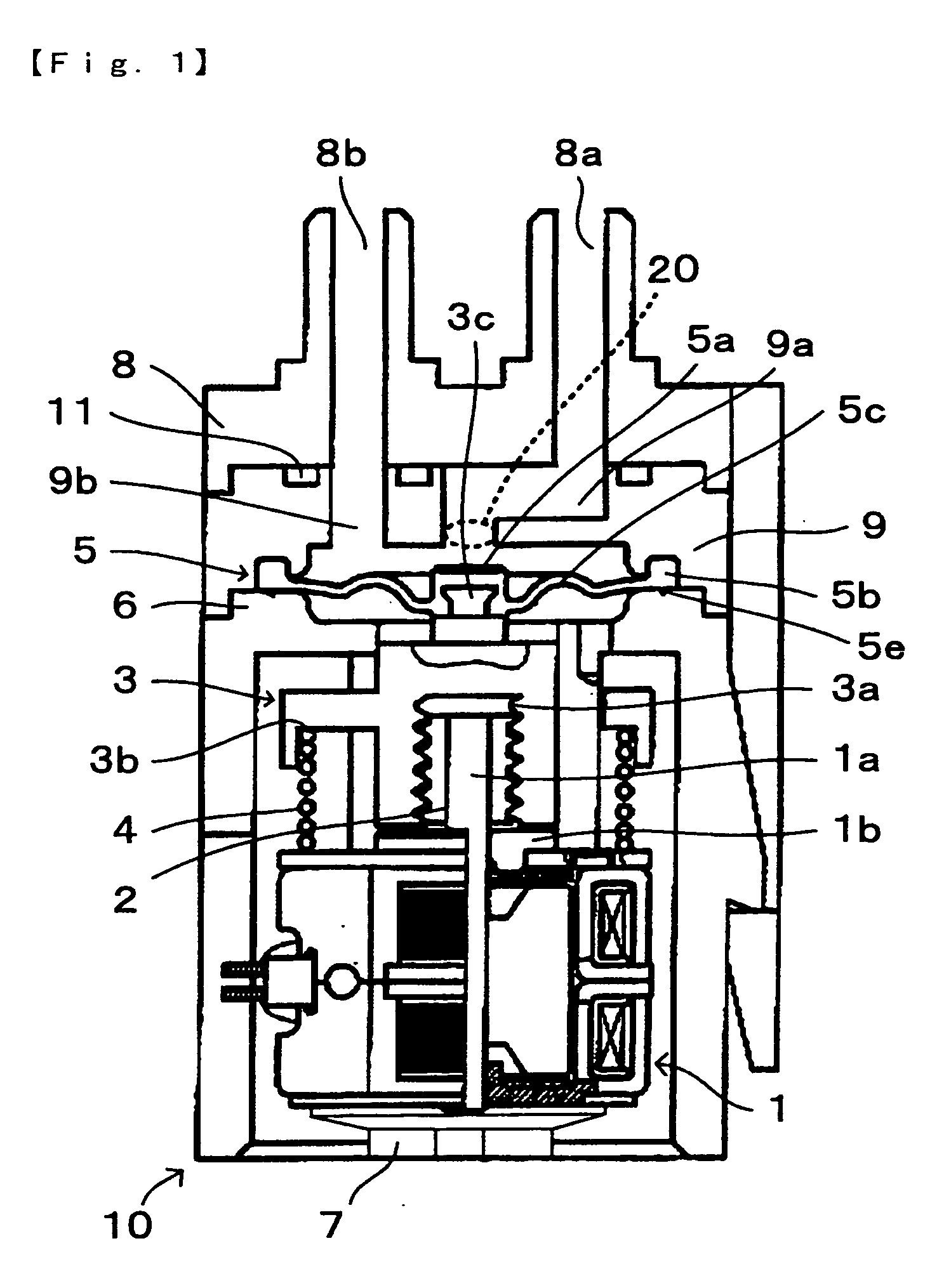
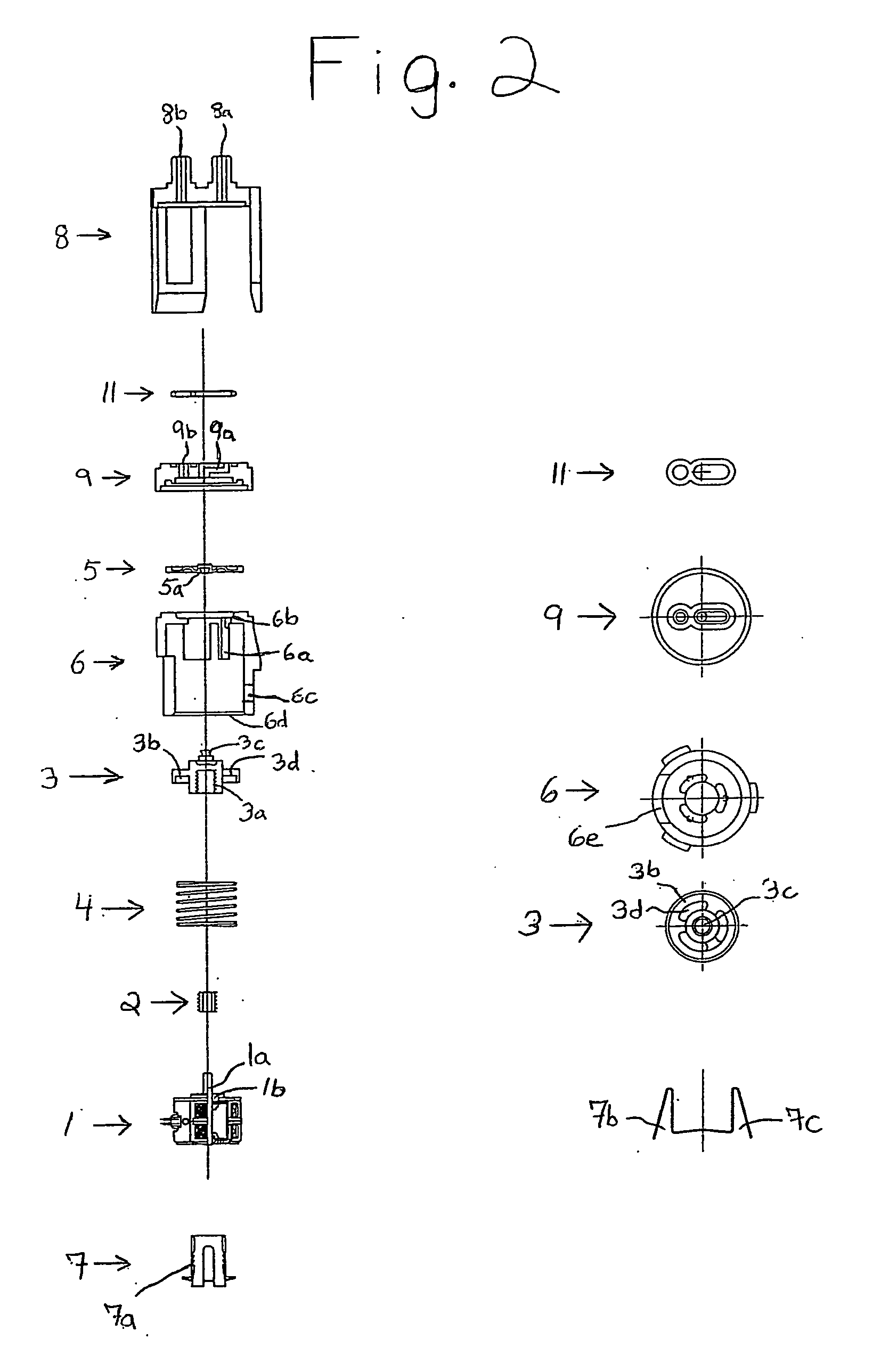
[0049]FIG. 1 is a longitudinal sectional view showing a valve drive device 10 in accordance with an embodiment of the present invention. FIG. 2 is an exploded view showing the valve drive device 10 in accordance with the embodiment. The left half side in FIG. 2 shows longitudinal sectional views of respective parts and the right half side in FIG. 2 shows plan views of the respective parts.

[0050] In FIGS. 1 and 2, the valve drive device 10 is mainly structured of a stepping motor 1 (hereinafter, simply referred to as a motor) as a drive source, a case 6 within which the motor 1 is provided, and a case 8 in which an inflow port 8a (inflow opening) for fluid and an outflow port 8b ...


PUM


Abstract

A valve drive device may include a motor, a rotational member rotated by the motor, a linearly moving member engaged with the rotary member, a converting mechanism for converting rotation of the rotational member into linear movement of the linearly moving member, a diaphragm valve for opening or closing an opening part by linearly moving member, and an urging member for closing the opening part through the diaphragm valve. The linearly moving member is linearly moved by the rotational member and the opening part is closed by the diaphragm valve in a state that the rotational member and the linearly moving member are in a non-engagement state. The valve drive device may be mounted on a pump having an inflow path and a plurality of outflow paths.

Description

CROSS REFERENCE [0001] The present invention claims priority under 35 U.S.C. §119 to Japanese Application No. 2005-356787 filed Dec. 9, 2005, which is incorporated herein by reference. FIELD OF THE INVENTION [0002] An embodiment of the present invention may relate to a valve drive device in which a valve hold member is moved to open or close a flow path by a motor, a control method for the valve drive device, and a pump utilizing the valve drive device. BACKGROUND OF THE INVENTION [0003] A refrigerator or an air conditioner is installed with a valve drive device in which a valve element is moved by a drive source such as a stepping motor to open and close a flow path for refrigerant to control temperature in a chamber which is in communication with the flow path. Further, a methanol type of fuel cell has been recently developed as a power supply for a mobile apparatus such as a notebook type of personal computer. A valve drive device is also utilized to adjust a flow rate of fuel wh...

Claims


Application Information

Patent Timeline
Patent Type & Authority Applications(United States)
IPC IPC(8): F16K31/02
CPCF04B7/0076F16K7/14F16K41/103F16K31/508F16K31/047
Inventor MURAMATSU, KENJI
Owner SANKYO SEIKI MFG CO LTD
Why Eureka
Try Eureka