Manufacturing method of stator, and stator

a manufacturing method and stator technology, applied in the direction of magnetic circuit rotating parts, magnetic circuit shapes/forms/construction, magnetic bodies, etc., can solve the problems of affecting the operation of the wire winding of the tooth, affecting the operation of the wire winding of each tooth, and failing to provide sufficient space for smooth wire winding operations, etc., to facilitate the winding of coils and shorten the connection wires

Active Publication Date: 2007-08-09
DENSO CORP
View PDF2 Cites 56 Cited by
  • Summary
  • Abstract
  • Description
  • Claims
  • Application Information

AI Technical Summary

Benefits of technology

[0011] It is an object of the present invention to provide a method for manufacturing a stator and a stator that facilitate the winding of coils around divisional cores and enable connection wires to be shortened.

Problems solved by technology

However, even with such greater space, teeth or coils adjacent to a tooth around which the wire is to be wound may interfere with the wire winding operation of the tooth.
Such adjacent teeth or coils may interfere with the wire winding operation of each tooth.
In this way, the first winding method and the second winding method both fail to provide sufficient space permitting smooth wire winding operations on the teeth.
Further, with the first winding method, the gap formed between the adjacent divisional cores further lengthens each connection wire.
Further, long connection wires require a complicated process for shaping the connection wires after the divisional cores are moved and arranged annularly.
Moreover, long connection wires increase the size of the stator in the axial direction.
However, the use of a bus bar or a current supply wire increases the number of components and increases the number of processes.

Method used


Image

  • Manufacturing method of stator, and stator
  • Manufacturing method of stator, and stator
  • Manufacturing method of stator, and stator

Examples


first embodiment

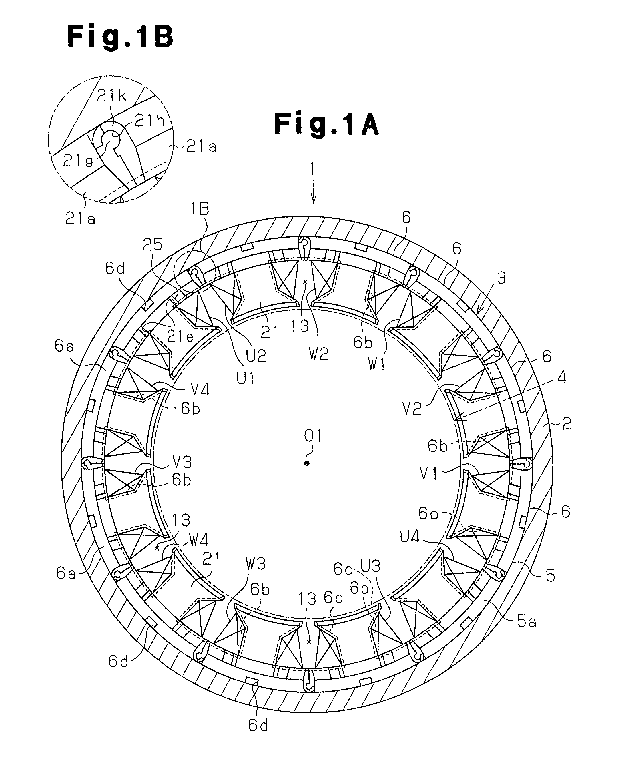
[0053] the present invention will now be described with reference to FIGS. 1A to 13.

[0054]FIG. 1A shows an inner rotor type brushless motor 1 according to a first embodiment of the present invention. The brushless motor 1 includes a housing case 2, a stator 3, and a rotor 4. The housing case 2 is cylindrical and has a closed bottom. The stator 3, which is cylindrical, is pressed fitted into the housing case 2 and fixed to the housing case 2. The rotor 4 is rotatably accommodated in the radially inward direction of the stator 3.

[0055] The rotor 4 shown by alternatively long and short dashed lines includes a plurality of magnets (not shown) that are arranged in the circumferential direction. The magnets face the stator 3. The stator 3 has a center axis O1.

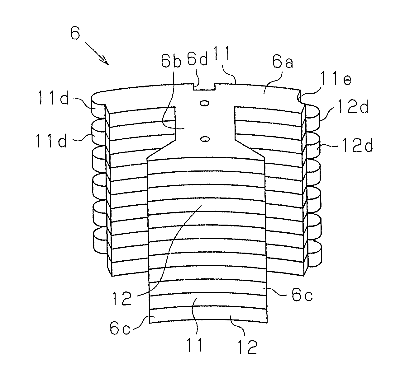
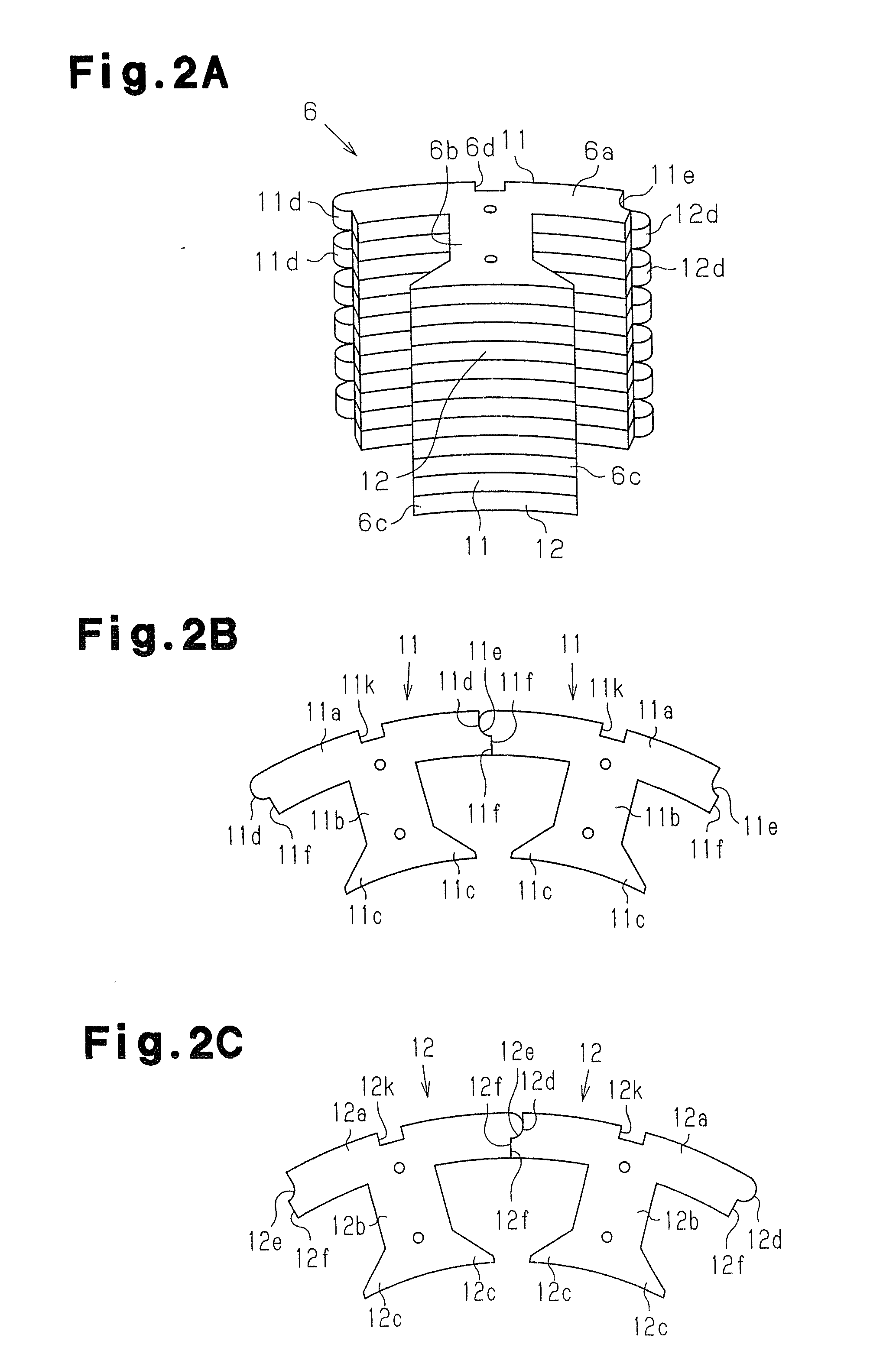
[0056] The stator 3 has a cylindrical stator core 5, which is press fitted into the housing case 2 and fixed to an inner circumferential surface of the housing case 2. The stator core 5 includes twelve divisional cores 6 that are a...


PUM

PropertyMeasurementUnit
angleaaaaaaaaaa
angleaaaaaaaaaa
diameteraaaaaaaaaa

Abstract

In a state in which a first divisional core and a second divisional core are arranged in a state spaced from each other and adjacent to each other, a first coil and a second coil are each wound around a tooth. The first coil and the second coil are in the same phase. In a state in which a plurality of divisional cores are arranged annularly so that their teeth are oriented in a radially inward direction, the first divisional core and the second divisional core are not adjacent to each other in the circumferential direction. A plurality of connection wires are shaped to converge at an end surface of a stator core. This facilitates the winding of the coils around the divisional cores. Further, the connection wires can be shortened.

Description

BACKGROUND OF THE INVENTION [0001] The present invention relates to a method for manufacturing a stator and a stator manufactured with the manufacturing method. [0002] Japanese Laid-Open Patent Publication No. 2002-176753 describes a method for manufacturing a stator for an inner-rotor type rotating electrical machine. The stator has an annular stator core. The stator core includes an annular portion and a plurality of teeth extending radially inward from the annular portion. A coil is wound around each tooth. A connection wire extends from one coil to another coil. [0003] The stator core may be divided into a plurality of divisional cores to increase the lamination factor of the coils. The divisional cores are formed by dividing the stator core in the circumferential direction. Each divisional core has a single tooth. [0004] The above publication discloses a first winding method and a second winding method for forming coils. With the first winding method, the plurality of divisiona...

Claims


Application Information

Patent Timeline
Patent Type & Authority Applications(United States)
IPC IPC(8): H02K1/28H02K1/12H02K15/00
CPCH02K1/148H02K3/28H02K3/522H02K15/095Y10T29/49071Y10T29/49011Y10T29/49073Y10T29/49012Y10T29/49009
Inventor SUGISHIMA, KAZUSHISUZUKI, AKIHIRO
Owner DENSO CORP
Why Eureka
Try Eureka