Push-push voltage controlled oscillator for obtaining differential signals

Inactive Publication Date: 2007-08-09
IND ACADEMIC COOP FOUNDATION YONSEI UNIV
View PDF5 Cites 38 Cited by
  • Summary
  • Abstract
  • Description
  • Claims
  • Application Information

AI Technical Summary

Benefits of technology

[0013] Accordingly, the present invention has been made keeping in mind the above problems occurring in the prior art, and an object of the present invention is to provide a push-push voltage-controlled oscillato

Problems solved by technology

Since it is known that, as elements become smaller, the errors of the elements increase, and there is a strong possibility that the error between a design frequency value and a manufacturing frequency value increases as the operating frequency of an oscillator increases.
However, this method has a problem in that an additional circuit is required and current consumption increases.
However, a conventional push-

Method used


Image

  • Push-push voltage controlled oscillator for obtaining differential signals
  • Push-push voltage controlled oscillator for obtaining differential signals
  • Push-push voltage controlled oscillator for obtaining differential signals

Examples


Embodiment Construction

[0032] Reference should now be made to the drawings, in which the same reference numerals are used throughout the different drawings to designate the same or similar components.

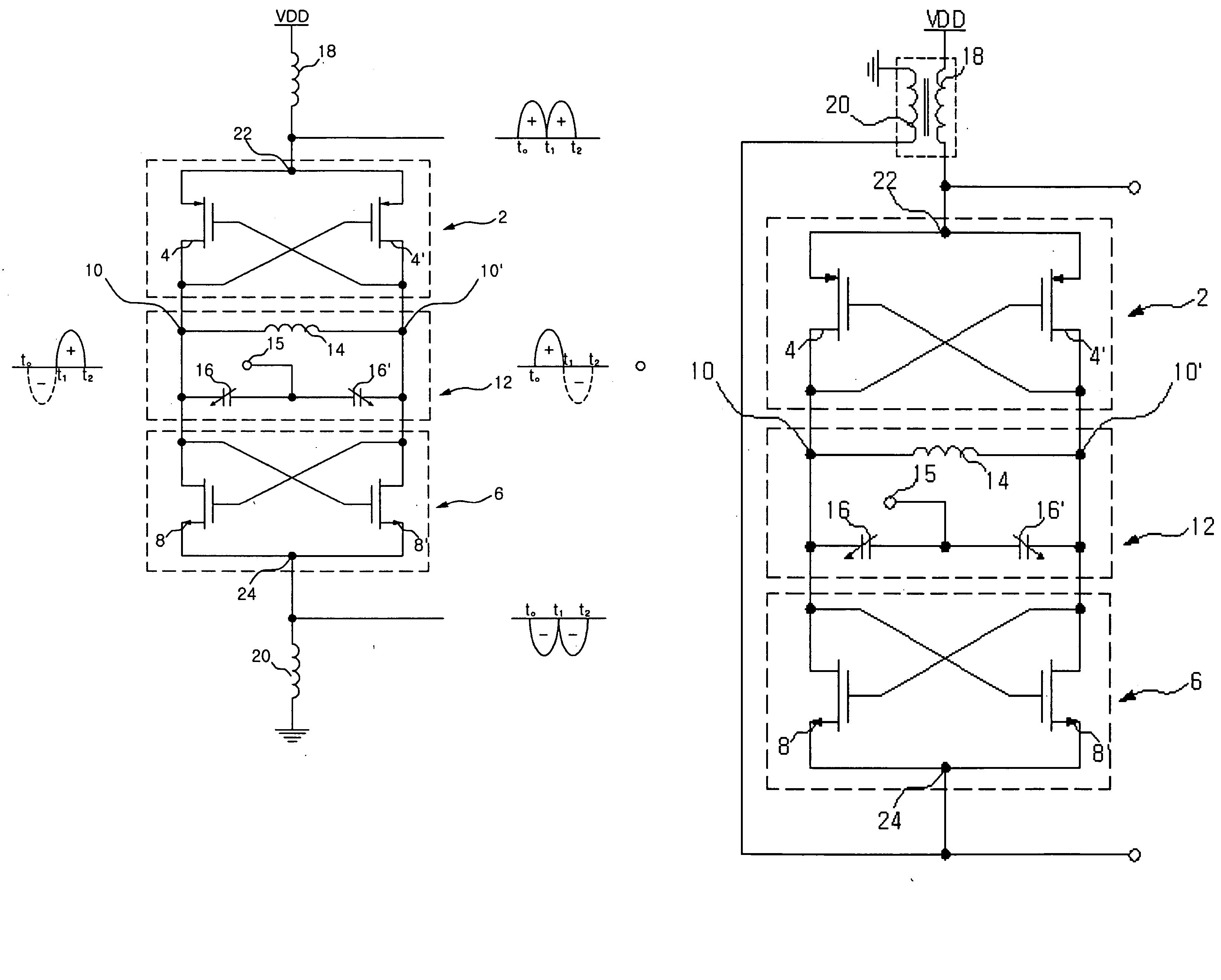
[0033]FIG. 3A and 3B are diagrams illustrating the structure of a push-push voltage controlled oscillator according to the present invention, FIGS. 4A and 4B are diagrams illustrating conceptual operation and simulated signal waveforms when the tank swing of the push-push voltage controlled oscillator according to the present invention is small, respectively, FIGS. 5A and 5B are diagrams illustrating conceptual operation and simulated signal waveforms when the tank swing of the push-push voltage controlled oscillator according to the present invention is large, respectively, FIG. 6 is a diagram illustrating the amplitude mismatch and phase mismatch of differential output signals due to the impedance element of the push-push voltage controlled oscillator according to the present invention, FIGS. 7A and 7B are...


PUM


Abstract

Disclosed herein is a push-push voltage controlled oscillator, including an LC resonance unit for determining a fundamental oscillation frequency; a first negative resistance generation means connected to the LC resonance unit and configured to generate negative resistance and deliver an output signal to a first common source terminal; a first impedance element for controlling an output signal of the first common source terminal; a second negative resistance generation means connected to the LC resonance unit and configured to generate negative resistance and deliver an output signal to a second common source terminal; and a second impedance element for controlling an output signal of the second common source terminal. The present invention obtains output signals having a frequency two times the fundamental resonance frequency of an LC resonator with differential signals having the same amplitude and opposite phases, so advantages occur in that high frequency differential outputs are obtained using a voltage controlled oscillator, and current consumption can be reduced because an additional circuit is not used.

Description

BACKGROUND OF THE INVENTION [0001] 1. Field of the Invention [0002] The present invention relates generally to a voltage controlled oscillator for a Radio Frequency (RF) integrated circuit and, more particularly, to a push-push voltage controlled oscillator that can obtain output signals having a frequency twice as high as the fundamental resonance frequency of an LC resonator with differential signals having the same amplitude and opposite phases. [0003] 2. Description of the Related Art [0004] Recently, markets for mobile communication terminals that not only operate in several frequency bands but also have various functions have developed domestically and abroad. [0005] Therefore, mobile communication terminals are being miniaturized in order to satisfy the demand of consumers, the parts of mobile communication terminals are being miniaturized, and the various parts of the RF system are also being miniaturized. [0006] Particularly, in order to implement a transceiver for high fre...

Claims


Application Information

Patent Timeline
IPC IPC(8): H03B5/08
CPCH03B5/1228H03B5/124H03B5/1265H03B5/1215A47J37/047A47J36/04
Inventor SHIN, HYUN-CHOLKIM, HYUN
Owner IND ACADEMIC COOP FOUNDATION YONSEI UNIV
Why Eureka
Try Eureka