Structured catalysts for pre-reforming hydrocarbons

Pending Publication Date: 2021-06-03
KOREA ADVANCED INST OF SCI & TECH +1
View PDF0 Cites 0 Cited by
  • Summary
  • Abstract
  • Description
  • Claims
  • Application Information

AI Technical Summary

Benefits of technology

The patent text describes the development of new structured catalysts that can improve the conversion of hydrocarbons, reduce the amount of catalyst needed, and increase the efficiency of the reaction. These catalysts contain a structured substrate and coatings made of cerium-gadolinium oxide and nickel. The technical effect of this invention is to provide better performance and more efficient use of catalysts in chemical reactions.

Problems solved by technology

However, using heavier fuels may be problematic as coking may occur on the anode of the SOFC.

Method used


Image

  • Structured catalysts for pre-reforming hydrocarbons
  • Structured catalysts for pre-reforming hydrocarbons
  • Structured catalysts for pre-reforming hydrocarbons

Examples


example 1

[0047]In Example 1, an experimental device is disclosed and described for testing various aspects of pre-reforming catalysts including embodiments of the structured catalysts.

[0048]FIG. 5 is a schematic illustration of an experimental system 500 for catalytic activity testing of pre-reforming catalysts, in accordance with various embodiments. In the system 500, fuel from container 502 is pumped by a first high performance liquid chromatography (HPLC) pump 504 through a first check valve 506 and is atomized by an ultrasonic injector 518 by mixing with air from container 510 in mixer 508. The air from container 510 passes through a first mass flow controller 512, second check valve 514, and first ball valve 516. Atomized fuel with air passes through ultrasonic injector 518 to reactor 520. The reactor 520 is a pre-reformer and can be a diesel autothermal reformer as shown in FIG. 5. Ultrasonic injector 518 includes pressure detecting gauge 521. Reactor 520 includes temperature detector...

example 2

[0050]In Example 2, various embodiments of structured pre-reforming catalysts for diesel pre-reforming were prepared. Preparation methods included various pretreatments and compositions of the structured catalysts. The structured catalysts were designed to produce methane rich gas from diesel fuel. Various embodiments of the structured catalysts consisted of CGO pre-coating layer and a catalyst layer over the CGO pre-coating layer. For comparison, structured catalysts without a CGO pre-coating layer were prepared. Without being bound by theory, the CGO pre-coating layer enhances adhesion and prevents undesired reactions. The Ni—Ru / CGO catalyst layer was formed over the CGO pre-coating layer.

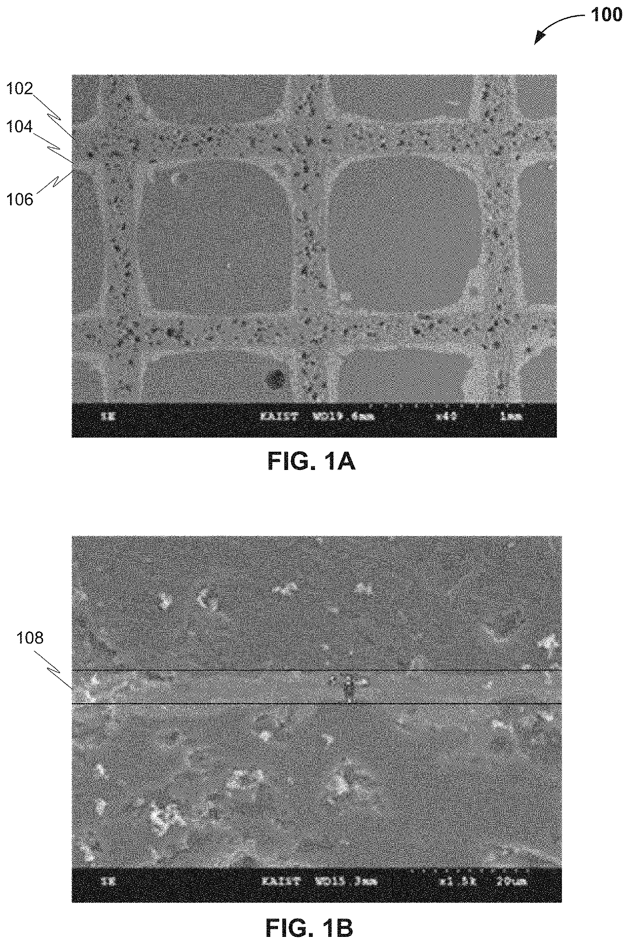
[0051]In this example, a structured catalyst was prepared by washing a structured substrate with a solution of 30% by weight of nitric acid to remove impurities from surfaces of the structured catalyst substrate. The structured substrate is as illustrated in FIG. 1A, prior to application of the c...

example 3

[0059]In Example 3, various embodiments of the structured catalysts were prepared with different numbers of coating layers of CGO pre-coating and the Ni—Ru / CGO catalyst coating layer. The purpose of varying the coating layer was to optimize the number of layers for the structured catalysts. The purpose of optimizing the number of coating layers was to determine whether there is an optimum number of coating layers to reduce the cost and the time of preparation of various embodiments of the structured catalysts for pre-reforming. The thickness of coating layer was observed using scanning electron microscope (SEM).

[0060]FIGS. 8A, 8B, and 8C schematically illustrate SEM images of three structured catalysts with five, seven, and nine layers of Ni—Ru / CGO coating layer respectively, in accordance with various embodiments. The thickness of the Ni—Ru / CGO coating layer was 6.0, 4.5, and 5.5 micrometers for coating layer numbers five, seven, and nine, respectively, as illustrated in FIGS. 8A, ...


PUM

PropertyMeasurementUnit
Timeaaaaaaaaaa
Electrical resistanceaaaaaaaaaa
Temperatureaaaaaaaaaa

Abstract

Provided herein are structured catalysts, methods of making structured catalysts, and methods of using structured catalysts for pre-reforming of hydrocarbons. The structured catalysts contain a structured catalyst substrate, a first coating containing cerium-gadolinium oxide; and a second coating containing nickel and cerium-gadolinium oxide.

Description

RELATED APPLICATIONS[0001]This application is a divisional application of and claims priority from U.S. Nonprovisional application Ser. No. 15 / 408,892, titled Structured catalysts for pre-reforming hydrocarbons, which was filed on Jan. 18, 2017 and is incorporated by reference in its entirety for purposes of United States patent practice.TECHNICAL FIELD[0002]The disclosure relates to structured catalysts for pre-reforming of hydrocarbons. More particularly, the disclosure relates to structured catalysts, methods of making structured catalysts, and methods of using structured catalysts for pre-reforming of hydrocarbons.BACKGROUND OF THE INVENTION[0003]Catalysts for chemical reactions generally include homogeneous solution catalysts and heterogeneous solid catalyst. Heterogeneous solid catalysts may include loose particle type catalysts and structured type catalysts, where the structured catalysts are characterized by having some type of formed or rigid structure having flow channels ...

Claims


Application Information

Patent Timeline
IPC IPC(8): B01J23/10C01B3/40B01J23/89B01J35/04B01J37/02B01J37/08B01J37/18B01J37/06H01M8/0612B01J37/00B01J23/83B01J23/00
CPCB01J23/10H01M2008/1293B01J23/894B01J35/04B01J37/024B01J37/08B01J37/18B01J37/06B01J37/0236H01M8/0618B01J37/0018B01J37/0217B01J23/83B01J23/002B01J37/0219B01J37/0036B01J37/0244C01B2203/0227C01B2203/066C01B2203/1064C01B3/40B01J2523/00C01B2203/1058C01B2203/1247Y02P20/52Y02E60/50B01J35/56B01J2523/3712B01J2523/375B01J2523/821B01J2523/847B01J23/00
Inventor KATIKANENI, SAI P.BAE, JOONGMYEONLEE, SANGHOBAE, MINSEOK
Owner KOREA ADVANCED INST OF SCI & TECH
Why Eureka
Try Eureka