RFID sensor device based on pulse-processing

Active Publication Date: 2007-08-09
QI BAOHUA
View PDF64 Cites 19 Cited by
  • Summary
  • Abstract
  • Description
  • Claims
  • Application Information

AI Technical Summary

Benefits of technology

[0009]The invention provides a sensing device based on RFID technology. In this device, sensing elements are incorporated into RFID tags, and sensing information is sent back to the interrogator with ID codes. Typically, in RFID communication, only digital signals are transferred by loading and unloading tags' antenna under CW. Consequently, in using RFID with sensors, an ADC is normally employed to convert the analog signals to digital signals before they can be sent to the interrogator, since most sensors convert the physical or chemical properties of an object into analog electric signals. In the

Problems solved by technology

It is not easy to obtain a precise reference voltage without using an embedded battery cell.
On the other hand, t

Method used


Image

  • RFID sensor device based on pulse-processing
  • RFID sensor device based on pulse-processing
  • RFID sensor device based on pulse-processing

Examples


Embodiment Construction

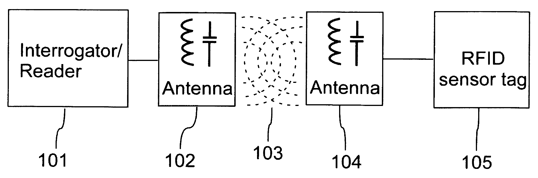
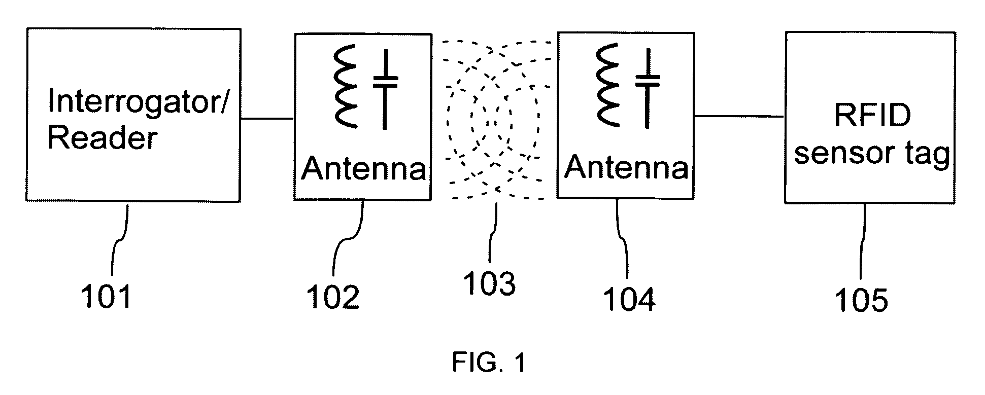
[0022]As depicted in FIG. 1, the RFID sensing system comprises an interrogator device 101 with an antenna 102 and an RFID sensor tag device 105 with an antenna 104. The RFID sensor tag device 105 has no internal power source. It gains power from a near field or far field RF103 generated by the interrogator device 101. After the tag device 105 is powered, it then changes the amplitude of the RF carrier with a sequence of code stored inside the device. The change in amplitude is detected by the interrogator device 101 and therein the patterns in the amplitude change, which contain the code information, are examined. The demodulated code is used for further data processing.

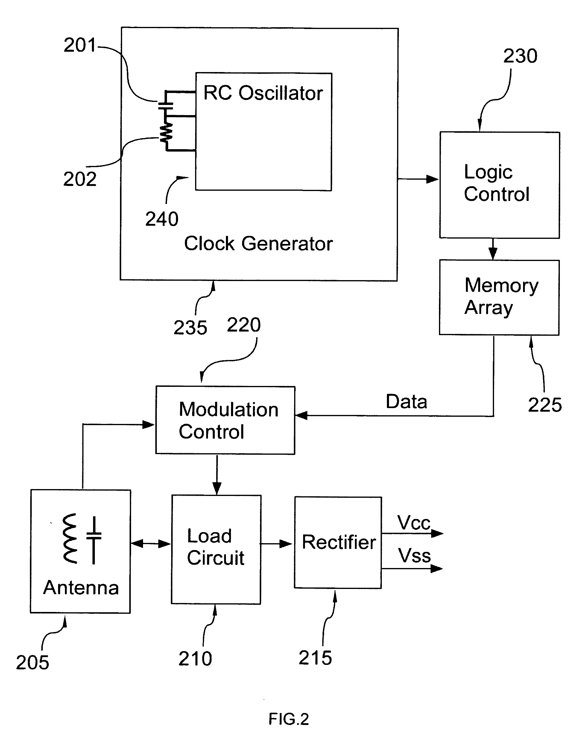
[0023]The block diagram of an embodiment of the RFID sensor tag device is shown in FIG. 2, in which, a clock generator 235, which includes an oscillator 240, is employed to provide a synchronous signal for a logic control block 230 to read the RFID code from a memory array 225. The RFID code is then encoded and modul...


PUM


Abstract

A radio frequency identification device having sensing elements incorporated in the clock generators of its tags, which generate a leading code and an identification code. In the interrogator, the leading code is detected and its pulse width is measured for calculating sensing values and the baud rate in receiving the identification code. No analog to digital converter is needed in digitizing sensing values and only discrete signals exist in sensing signal generation and communication. The tag device is insensitive to variations in its power supply voltage obtained from a continuous wave RF carrier.

Description

[0001]This present application claims priority from U.S. provisional application No. 60 / 763,315 having the same tile as the present invention and filed on Jan. 30, 2006.CROSS-REFERENCE TO RELATED APPLICATIONS[0002]Not ApplicableSTATEMENT REGARDING FEDERALLY SPONSORED RESEARCH OR DEVELOPMENT[0003]Not ApplicableREFERENCE TO SEQUENCE LISTING, A TABLE, OR A COMPUTER PROGRAM LISTING COMPACT DISC APPENDIX[0004]Not ApplicableFIELD OF THE INVENTION[0005]This invention relates to radio frequency identification (RFID) devices, and more particularly, to RFID based sensors, the data acquired from which is read by an interrogator.BACKGROUND OF THE INVENTION[0006]Radio frequency identification devices generally comprise RF tags and a read-out device that is usually called interrogator or integration reader. The interrogator generates a continuous wave (CW) RF carrier that is used by the tag as a power source to modify the amplitude of the CW carrier by loading and unloading its antenna with store...

Claims


Application Information

Patent Timeline
IPC IPC(8): G08B1/08G08B13/14H04Q5/22
CPCH04Q9/00
Inventor QI, BAOHUA
Owner QI BAOHUA
Why Eureka
Try Eureka