
Retardation plate with protective film, method of manufacturing thereof, pressure-sensitive adhesive type retardation plate with protective film, and pressure-sensivie adhesive type optical material with protective film

a technology of retardation plate and protective film, which is applied in the direction of instruments, other domestic articles, synthetic resin layered products, etc., can solve the problems of retardation plate local change, easy folding, and difficulty in lamination with other optical materials, and achieves easy separation, good yield, and good handling

Inactive Publication Date: 2007-08-09
NITTO DENKO CORP
View PDF3 Cites 14 Cited by
  • Summary
  • Abstract
  • Description
  • Claims
  • Application Information

AI Technical Summary

Benefits of technology

The present invention relates to a retardation plate with protective films that can suppress curling and has good workability and peelability even when using a thin retardation plate. The protective films are sequentially laminated on the retardation plate with low adhesive strength to prevent separation or peeling. The invention also provides a method of manufacturing the retardation plate with protective films and a pressure-sensitive adhesive type optical material with protective films.

Problems solved by technology

As the thickness of retardation plates is reduced, however, a cut sheet (a retardation plate) can be significantly curled due to a slight difference in tension when a protective film is laminated on the retardation plate, so that there may be a problem in which the lamination with other optical materials becomes difficult.
Another problem also occurs in which when the cut sheet is handled, local stress is applied due to folding or the like so that the retardation plate can undergo a local change in retardation or can be frequently ruptured or broken.
However, as the thickness of retardation plates is reduced, curling becomes significant, so that folding can easily occur, or the plates can easily suffer flaws, even when such a protective film is used.
Therefore, the protection performance of the protective film has become insufficient.
In this method, however, the capability of laminating with a thin retardation plate can be generally reduced so that the protective film can separate or peel off.
However, such an increased adhesive strength prevents the protective film from having the required peelability.
However, there is a significant difference in elastic modulus between the polyethylene terephthalate film and the thin retardation plate, and therefore the problem of curling tendency cannot be overcome.
In general, the adhesive strength between the protective film and the thin retardation plate is often so high that it can be difficult to separate the protective film.
In such a case, however, separation or peeling can occur due to the lamination performance with the thin retardation plate.

Method used

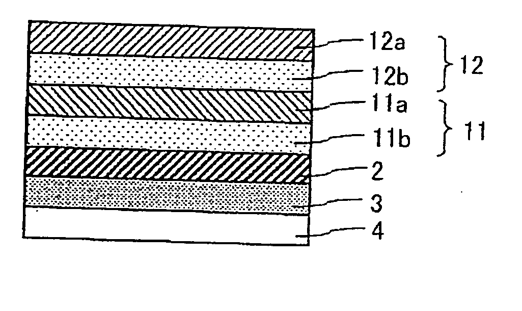
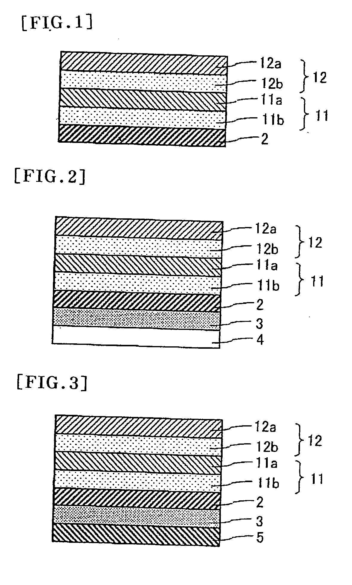

Image

  • Retardation plate with protective film, method of manufacturing thereof, pressure-sensitive adhesive type retardation plate with protective film, and pressure-sensivie adhesive type optical material with protective film
  • Retardation plate with protective film, method of manufacturing thereof, pressure-sensitive adhesive type retardation plate with protective film, and pressure-sensivie adhesive type optical material with protective film
  • Retardation plate with protective film, method of manufacturing thereof, pressure-sensitive adhesive type retardation plate with protective film, and pressure-sensivie adhesive type optical material with protective film

Examples


example 1

[0121] The retardation plate a (200 mm×300 mm) was fixed on a SUS plate with a temporary fixing tape, and then the protective film A (serving as the first protective film) was attached to the surface of the retardation plate a with a roll laminator under a tension of 10 N / m at a laminating speed of 1 m / minute. The protective film C (serving as the second protective film) was further attached to the first protective film by the same attaching method as for the first protective film to form a retardation plate with protective films with a size of 180 mm×280 mm. The retardation plate with protective films was finally obtained by cutting the temporary fixing tape and other parts, 20 mm in length and 20 mm in width.


PUM

PropertyMeasurementUnit
adhesive strengthsaaaaaaaaaa
adhesive strengthaaaaaaaaaa
thicknessaaaaaaaaaa

Abstract

A retardation plate with protective films of the present invention comprises a retardation plate; and at least two protective films that each comprise a base film and a pressure-sensitive adhesive layer formed on one side of the base film and are sequentially laminated on the retardation plate, wherein the first protective film laminated on the retardation plate differs in adhesive strength to adherend from the protective film or films other than the first protective film, and the first protective film has the lowest adhesive strength. The retardation plate with protective films can suppress curling and has good workability and good peelability even when using a thin retardation plate.

Description

TECHNICAL FIELD [0001] The present invention relates to a retardation plate with protective films and a method of manufacturing thereof. The retardation plate may be used for a variety of image displays such as liquid crystal displays, organic electroluminescent displays and plasma display panels. In a manufacturing process, the retardation plate with protective films can form a retardation plate-laminated product or a retardation plate-laminated product without impairing workability or appearance. [0002] The present invention also relates to a pressure-sensitive adhesive type retardation plate with protective films including the retardation plate with protective films and a pressure-sensitive adhesive layer formed thereon. The pressure-sensitive adhesive type retardation plate with protective films may be used to form a pressure-sensitive adhesive type optical material with protective films having a laminated optical material including an optical film such as a polarizing plate for...

Claims


Application Information

Patent Timeline
Patent Type & Authority Applications(United States)
IPC IPC(8): G02F1/1335B32B7/022
CPCB29D11/0073B32B2457/20B32B7/12B32B37/0015B32B37/02B32B37/12B32B2307/40G02B1/105B32B7/06B32B27/08B32B27/306B32B27/308B32B27/32B32B27/36B32B27/365B32B2307/412B32B2307/42B32B2307/516B32B2307/518B32B2307/708B32B2307/748B32B7/02G02B1/14B32B7/022
Inventor YAMAOKA, TAKASHIHIGAMI, MASAO
Owner NITTO DENKO CORP
Learn More