Polarized light emitting light guide plate, method of manufacturing the same and illuminator for flat panel display device using polarized light emitting light guide plate

a technology of light guide plate and light guide plate, which is applied in the direction of polarising elements, lighting and heating apparatus, instruments, etc., can solve the problems of low light use efficiency, low light use efficiency of liquid crystal displays, and the use of 5% of conventional liquid crystal displays

Inactive Publication Date: 2007-08-09
SAMSUNG DISPLAY CO LTD
View PDF10 Cites 21 Cited by
  • Summary
  • Abstract
  • Description
  • Claims
  • Application Information

AI Technical Summary

Benefits of technology

[0011]Exemplary embodiments of the present invention provide a polarized light emitting light guide plate and a method of manufacturing the same tha

Problems solved by technology

However, conventional liquid crystal displays only use about 5% of the light emitted from a light source.
Such low light use efficiency is mainly due to light absorption in polarization plates and color filters of the liquid crystal display.
Specifically, since absorptive polarization plates, which are disposed on both sides of the liquid crystal display, absorb about 50% of unpolarized incident light, the absorptive polarization plates are the greatest cause of the low light use efficiency of the liquid crystal display.
However, this additional reflective polarization film is expensive, and the increase in the light use efficiency resulting from its usage is limited due to the lack of a polarization conversion member.
However, when manufacturing the conventional polarized light emit

Method used


Image

  • Polarized light emitting light guide plate, method of manufacturing the same and illuminator for flat panel display device using polarized light emitting light guide plate
  • Polarized light emitting light guide plate, method of manufacturing the same and illuminator for flat panel display device using polarized light emitting light guide plate
  • Polarized light emitting light guide plate, method of manufacturing the same and illuminator for flat panel display device using polarized light emitting light guide plate

Examples


Embodiment Construction

[0032]The present invention will now be described more fully with reference to the accompanying drawings, in which exemplary embodiments of the invention are shown.

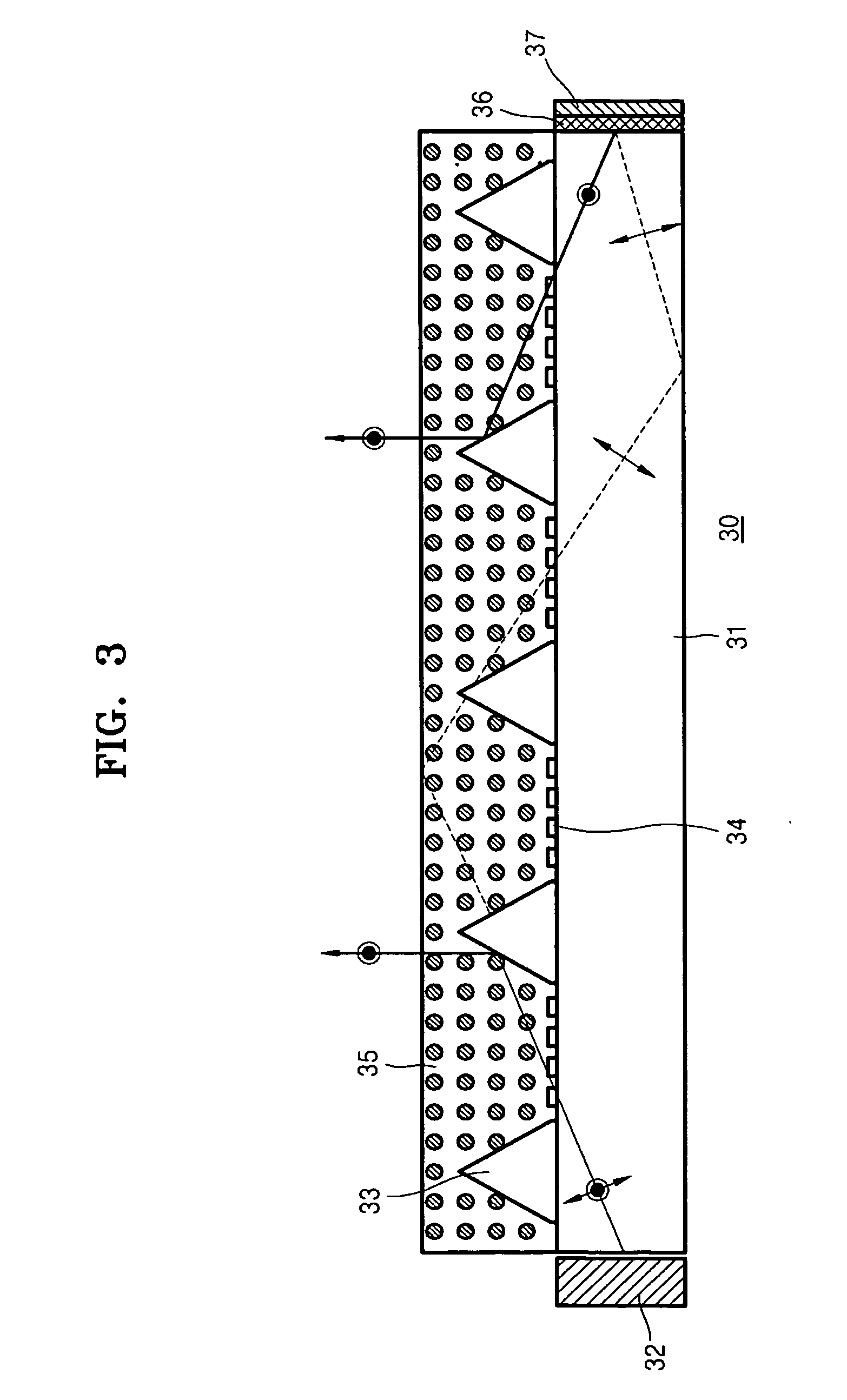
[0033]FIG. 3 illustrates an illuminator 30 for a flat panel display device according to an exemplary embodiment of the present invention. Referring to FIG. 3, the polarized light emitting light guide plate of the present embodiment includes a transparent substrate 31 in which incident light from a lateral side thereof travels, an anisotropic liquid crystal polymer layer 35 formed on an upper surface of the transparent substrate 31, and a polarization separation microstructure 33 that is formed at an interface between the transparent substrate 31 and the liquid crystal polymer layer 35.

[0034]According to an embodiment of the present invention, the transparent substrate 31 is formed of an optically isotropic material having a refractive index that is independent of polarization. For example, the transparent substrate 31 may...


PUM


Abstract

A polarized light emitting light guide plate includes: a transparent substrate of optically isotropic material, in which the light incident through a lateral side thereof travels; an anisotropic liquid crystal polymer layer formed on an upper surface of the substrate and having first and second refractive indices with respect to first and second perpendicular polarization components; and a polarization separation microstructure formed at an interface between the transparent substrate and the liquid crystal polymer layer, which refracts or reflects the first polarization component and transmits the second polarization component. The refractive index of the polarization separation microstructure is substantially equal to the refractive index of the substrate; the first refractive index of the liquid crystal polymer layer is greater than the refractive index of the substrate, and the second refractive index of the liquid crystal polymer layer light is substantially equal to the refractive index of the substrate.

Description

CROSS-REFERENCE TO RELATED PATENT APPLICATION[0001]This application claims the benefit of Korean Patent Application No. 10-2006-0012032, filed on Feb. 8, 2006 in the Korean Intellectual Property Office, the disclosure of which is incorporated herein in its entirety by reference.BACKGROUND OF THE INVENTION[0002]1. Field of the Invention[0003]Apparatuses and methods consistent with the present invention relate to a polarized light emitting light guide plate, a method of manufacturing the same, and an illuminator for a flat panel display device using the polarized light emitting light guide plate, and more particularly, to a polarized light emitting plate which can emit light with a predetermined polarized component, a method of manufacturing the same, and an illuminator for a flat panel display device using the polarized light emitting light guide plate.[0004]2. Description of the Related Art[0005]Flat panel displays are classified into emissive displays, which form images by emitting...

Claims


Application Information

Patent Timeline
IPC IPC(8): G02B27/28
CPCG02B6/0038G02F1/13362G02B6/0056G02F1/1335
Inventor HWANG, SEONG-MOWEE, DONG-HONAM, SEUNG-HO
Owner SAMSUNG DISPLAY CO LTD
Why Eureka
Try Eureka