Methods and apparatus for measuring the flapping deformation of insect wings

a technology of insect wings and measuring instruments, which is applied in the field of computer vision systems and methods for measuring the flapping motion of insect wings, can solve the problems of difficult simultaneous capture of insect flight images by different cameras, the deformation of a unilateral wing cannot be measured, and the study of the flapping deformation of bilateral wings is not yet complete, etc., to achieve excellent mobility, high flapping frequency, and large stroke amplitude

Active Publication Date: 2007-08-09
BEIHANG UNIV
View PDF1 Cites 39 Cited by
  • Summary
  • Abstract
  • Description
  • Claims
  • Application Information

AI Technical Summary

Benefits of technology

[0009] Accordingly, it is an object of the present invention to provide a high-performance apparatus and method being capable of measuring three-dimensio

Problems solved by technology

In recent years, many insects have been studied, but most researches were aimed at the unilateral wing, and detailed study on the flapping deformation of bilateral wings are not yet achieved, especially for the insects with high flapping-frequency, large stroke-amplitude and excellent mobility, such as fly and honeybee.
This problem is called blind observation region of camera, which results in that only the deformation of a uni

Method used


Image

  • Methods and apparatus for measuring the flapping deformation of insect wings
  • Methods and apparatus for measuring the flapping deformation of insect wings
  • Methods and apparatus for measuring the flapping deformation of insect wings

Examples


Embodiment Construction

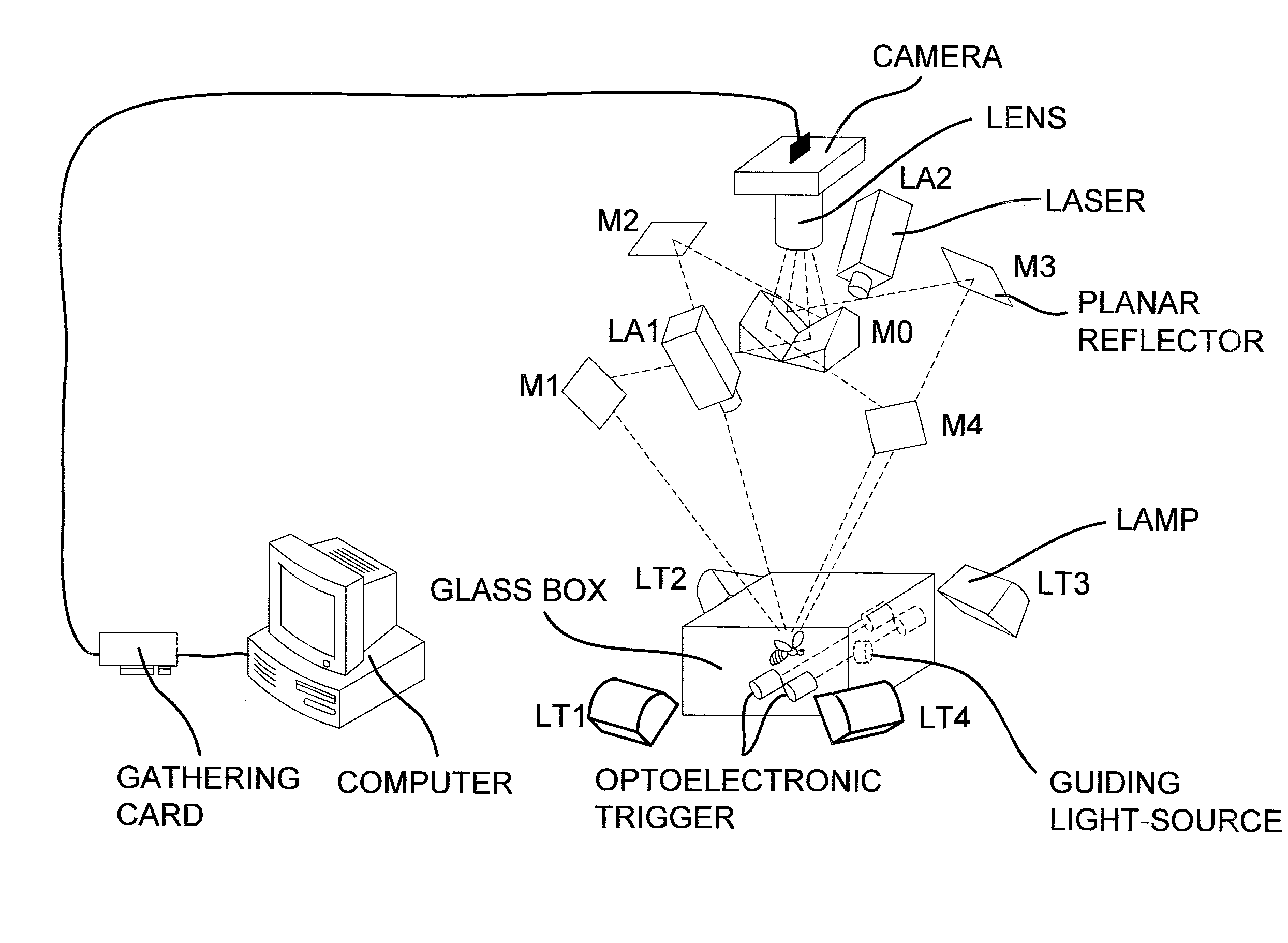
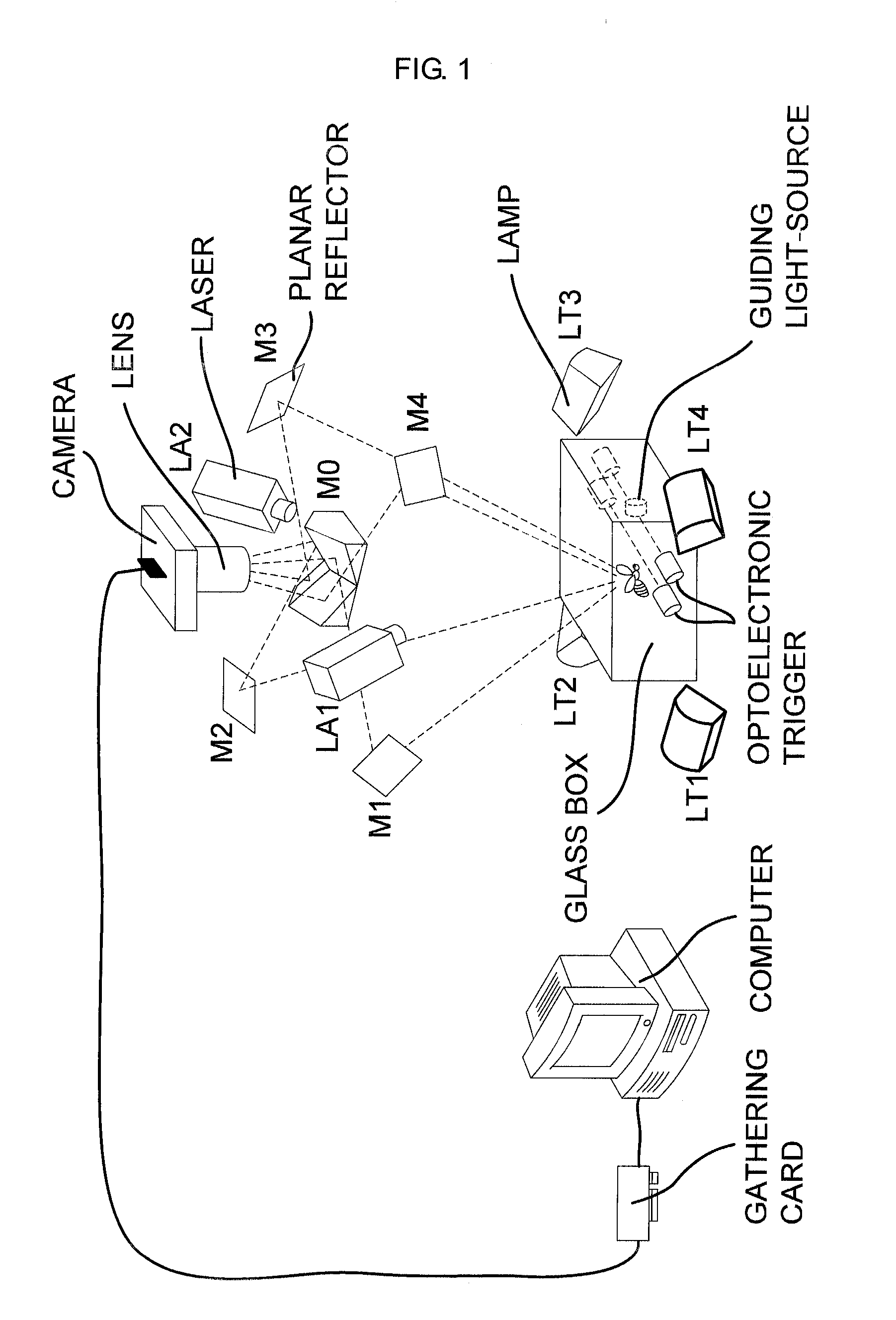
[0024]FIG. 1 shows the configuration of insect-wings deformation measurement system, which consists of a high-speed CMOS camera, a close focusing lens, an image gathering card, a geometric optic unit including four planar reflectors (M1, M2, M3, M4) and a polyhedral reflector with four planes of reflection (M0), double laser-sheet sources (LA1 and LA2), four background lamps (LT1 and LT2), a glass box for insect free-flight and an optoelectronic equipment for leading the flight of insect.

[0025] As shown by FIG. 1, camera, lens and gathering card compose the image capturing equipment to capture the image sequences of insect-flight. The high-speed CMOS camera is produced by America Redlake Co. with maximum capture frequency of 10,000 f / s. The close focusing lens is produced by Japan Nikon Co. with focus length of 55 mm.

[0026] The geometric optic unit is a key component in this system. The polyhedral reflector M0 has four reflection planes. M1, M2, M3 and M4 are four planar reflector...


PUM


Abstract

The present invention relates to a high-performance computer vision system and method for measuring the wings deformation of insects with high flapping-frequency, large stroke-amplitude and excellent mobility during free-flight. A geometrical optic unit composed of a polyhedral reflector with four reflection-planes and four planar reflectors is used to image one high-speed CMOS camera to four virtual cameras, combined with double laser-sheet sources, multiple virtual stereo and structured-light sensors are available to observe the free-flight of insect at different viewpoints simultaneously. In addition, an optoelectronic guiding equipment is included to lead the free-flight of insect and trigger the camera to capture the image sequences of insect-flight automatically. The deformation of insect-wings can be reconstructed by the spatial coordinates of wing-edges and the distorted light-lines projected on the surface of wings.

Description

FIELD OF THE INVENTION [0001] The present invention relates to a computer vision system and method for measuring the flapping motion of insect wings, and more particularly to a computer vision system composed of multiple virtual stereo and structured-light sensors to observe the free-flight of insects and reconstruct the three-dimensional deformation of bilateral wings. [0002] In addition, the invention relates to an optoelectronic guiding equipment and method to lead the fee-flight of insect and trigger the high-speed camera to capture the image sequences automatically. BACKGROUND OF THE INVENTION [0003] Detailed information on the flapping motion of insect wings is essential for aerodynamic modeling of insect-flight and the aerodynamic mechanisms being employed in micro-air vehicles (MAV). In recent years, many insects have been studied, but most researches were aimed at the unilateral wing, and detailed study on the flapping deformation of bilateral wings are not yet achieved, es...

Claims


Application Information

Patent Timeline
IPC IPC(8): G01B11/16
CPCB64C33/02G01B11/2545G01B11/2513G01B11/167
Inventor ZHANG, GUANGJUNCHEN, DAZHIWANG, YINGZHOU, FUQIANGWEI, ZHENZHONG
Owner BEIHANG UNIV
Why Eureka
Try Eureka