Leaned deswirl vanes behind a centrifugal compressor in a gas turbine engine

a gas turbine engine and centrifugal compressor technology, applied in the direction of machines/engines, stators, liquid fuel engines, etc., can solve the problems of insufficient condition of air flow, inability to meet the requirements of newer aircraft size, and relatively time-consuming and costly assembly manufacturing

Inactive Publication Date: 2007-08-09
HONEYWELL INT INC
View PDF17 Cites 32 Cited by
  • Summary
  • Abstract
  • Description
  • Claims
  • Application Information

AI Technical Summary

Problems solved by technology

However, it has been found that these deswirl assemblies generate greater flow angle variation across the span of the flowpath at the deswirl vane leading edge and therefore may not adequately condition air flow to a sufficiently low mach number in an acceptably efficient manner unless the overall axial length and / or radial envelope of the assembly is increased.
Because engines are continually designed to be smaller, the size increase may not be acceptable in newer aircraft.
However, although this configuration optimizes airflow through the deswirl assembly, manufacture of the assembly is relatively time-consuming and costly because each vane may need to be individually formed and shaped.

Method used


Image

  • Leaned deswirl vanes behind a centrifugal compressor in a gas turbine engine
  • Leaned deswirl vanes behind a centrifugal compressor in a gas turbine engine
  • Leaned deswirl vanes behind a centrifugal compressor in a gas turbine engine

Examples


Embodiment Construction

[0015] Before proceeding with the detailed description, it is to be appreciated that the described embodiment is not limited to use in conjunction with a particular type of turbine engine. Thus, although the present embodiment is, for convenience of explanation, depicted and described as being implemented in a multi-spool turbofan gas turbine jet engine, it will be appreciated that it can be implemented in various other types of turbines, and in various other systems and environments.

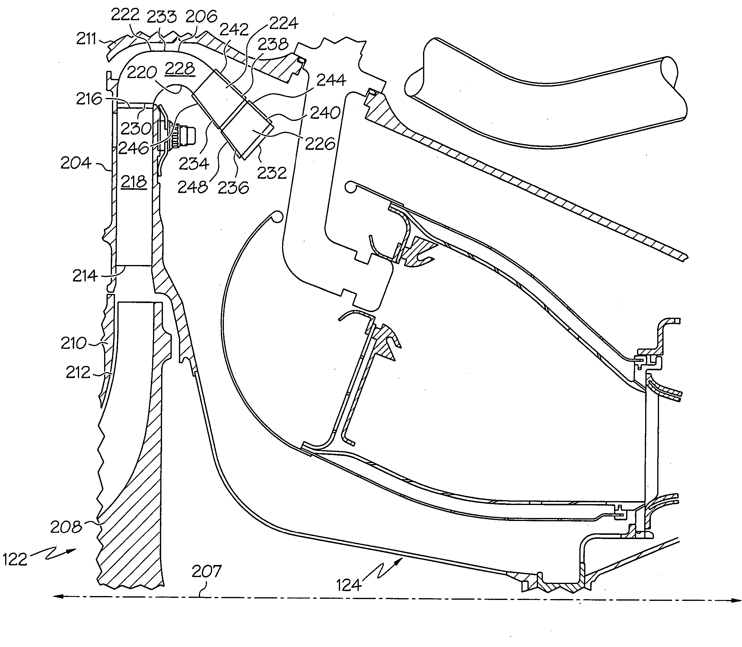
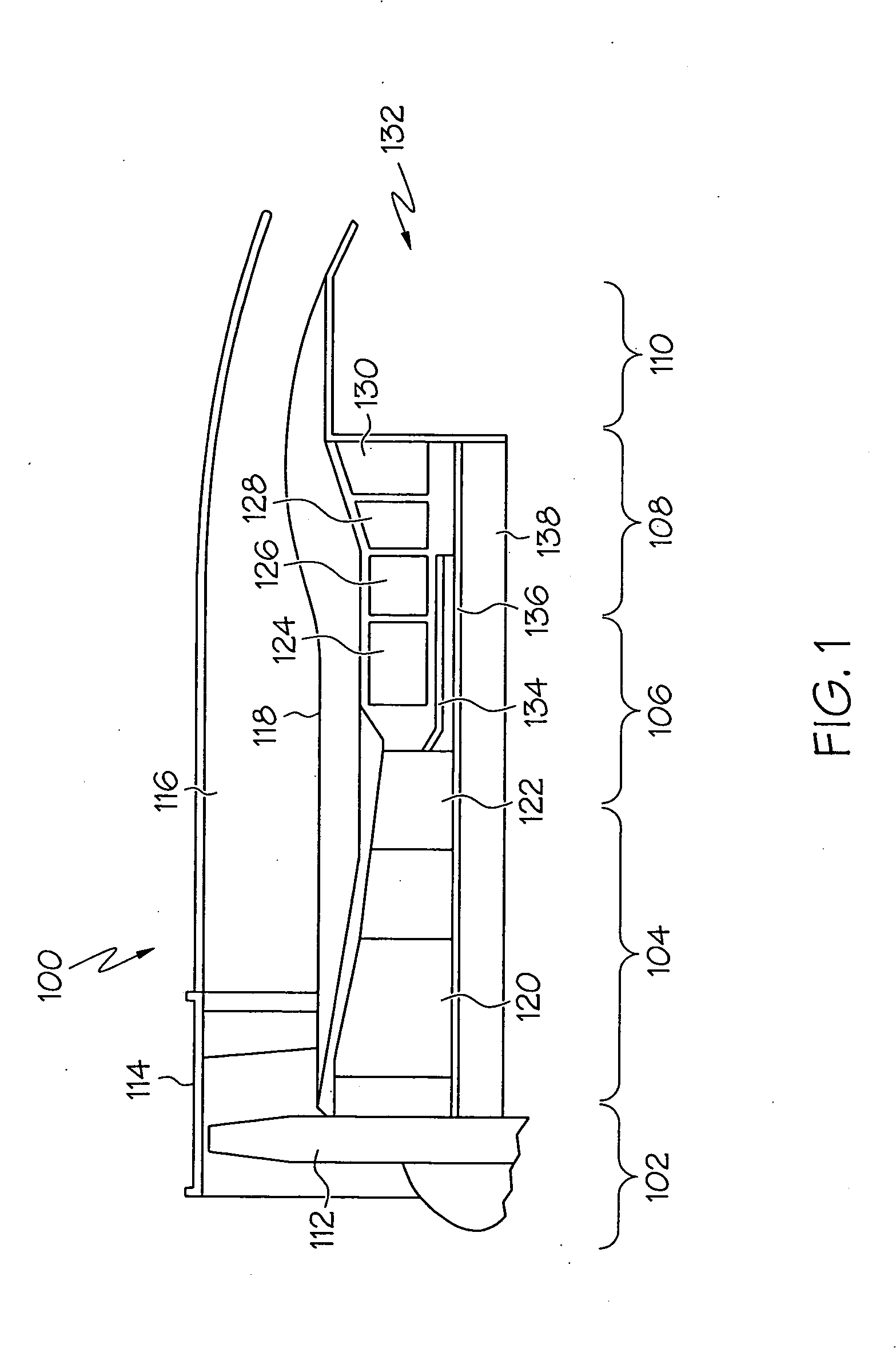
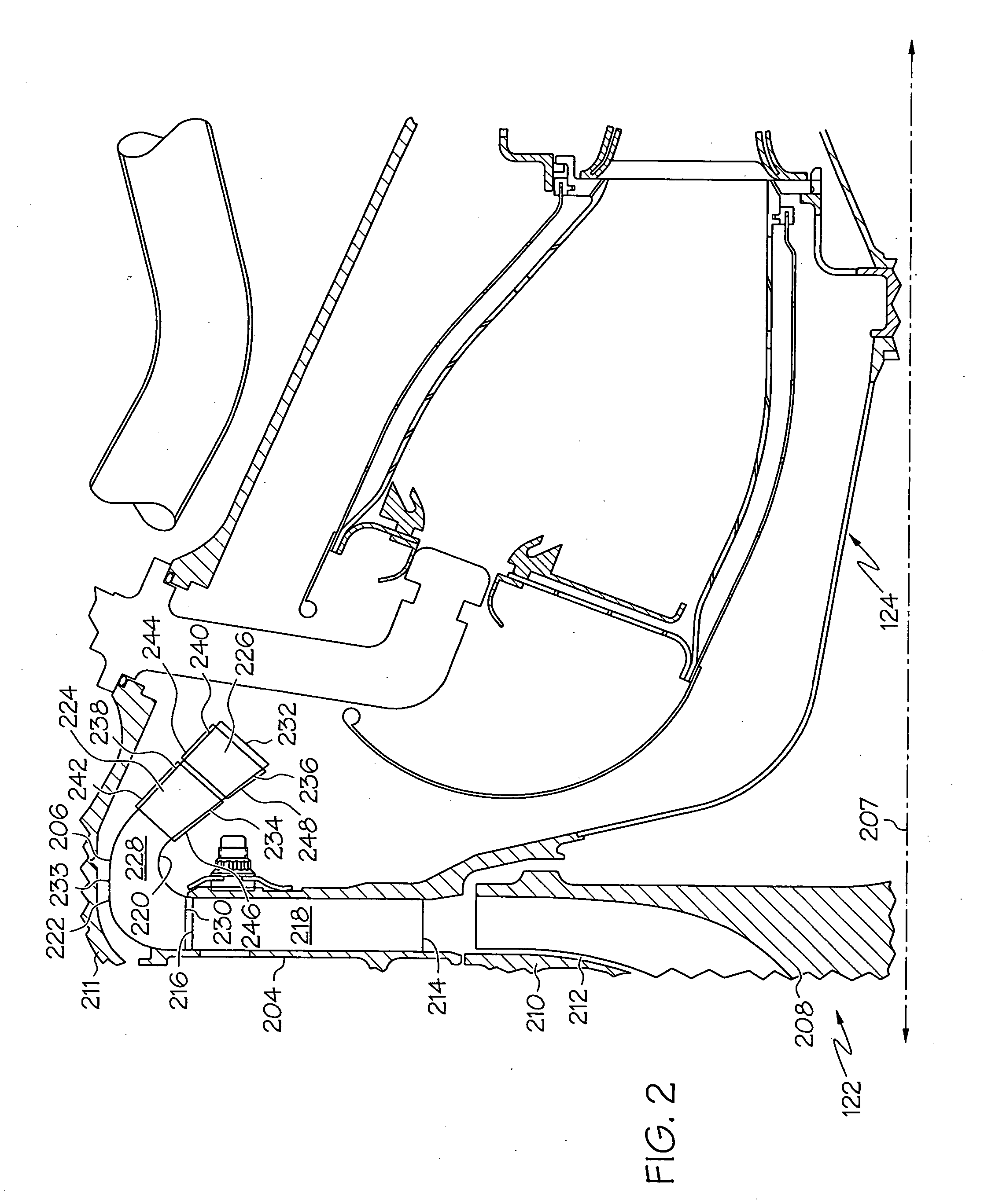
[0016] An exemplary embodiment of a multi-spool turbofan gas turbine jet engine 100 is depicted in FIG. 1, and includes an intake section 102, a compressor section 104, a combustion section 106, a turbine section 108, and an exhaust section 110. The intake section 102 includes a fan 112, which is mounted in a fan case 114. The fan 112 draws air into the intake section 102 and accelerates it. A fraction of the accelerated air exhausted from the fan 112 is directed through a bypass section 116 disposed b...


PUM


Abstract

A compressor includes a deswirl assembly to improve aerodynamic coupling with the combustor. The assembly includes an annular housing and a plurality of vanes. The annular housing includes an inner and an outer annular wall disposed concentric to each other, and a flowpath defined therebetween. The plurality of vanes is disposed in the flowpath in a substantially annular pattern. Each vane has a leading edge, a trailing edge, a convex surface, and concave surface, and each of the convex and concave surfaces extends between the leading and trailing edges. Additionally, each vane extends between and is angled relative to the inner and the outer annular walls such that the concave surface faces the outer annular wall and the convex surface faces the inner annular wall. The vanes preferably have a uniform axial cross section for ease of manufacturing.

Description

TECHNICAL FIELD [0001] The present invention relates to a gas turbine engine and, more particularly, to a deswirl assembly having leaned deswirl vanes for use in the gas turbine engine. BACKGROUND [0002] A gas turbine engine may be used to power various types of vehicles and systems. A typical gas turbine engine includes a fan section, a compressor section, a combustor section, a turbine section, and an exhaust section. The fan section induces air from the surrounding environment into the engine and accelerates a fraction of the air toward the compressor section. The compressor section compresses the pressure of the air to a relatively high level and directs the air to the combustor section. A steady stream of fuel is injected into the combustor section, and the injected fuel is ignited to significantly increase the energy of the compressed air. The high-energy compressed air then flows into and through the turbine section, causing rotationally mounted turbine blades therein to rota...

Claims


Application Information

Patent Timeline
Patent Type & Authority Applications(United States)
IPC IPC(8): F01D9/00
CPCF01D9/02F04D29/444F05D2240/127F05D2240/12F05D2240/128F05D2240/30
Inventor NOLCHEFF, NICK A.SLOVISKY, JOHN A.PLUMMER, MICHON N.
Owner HONEYWELL INT INC
Why Eureka
Try Eureka