
Surgical implant and manufacturing method

a manufacturing method and implant technology, applied in the field of surgical implants, can solve the problems of difficult, sometimes even impossible, to adequately gain tissue information, and difficult to shape in situ into the required shape, and achieve the effect of higher elongation at break

Inactive Publication Date: 2007-08-09
INION
View PDF4 Cites 194 Cited by
  • Summary
  • Abstract
  • Description
  • Claims
  • Application Information

AI Technical Summary

Benefits of technology

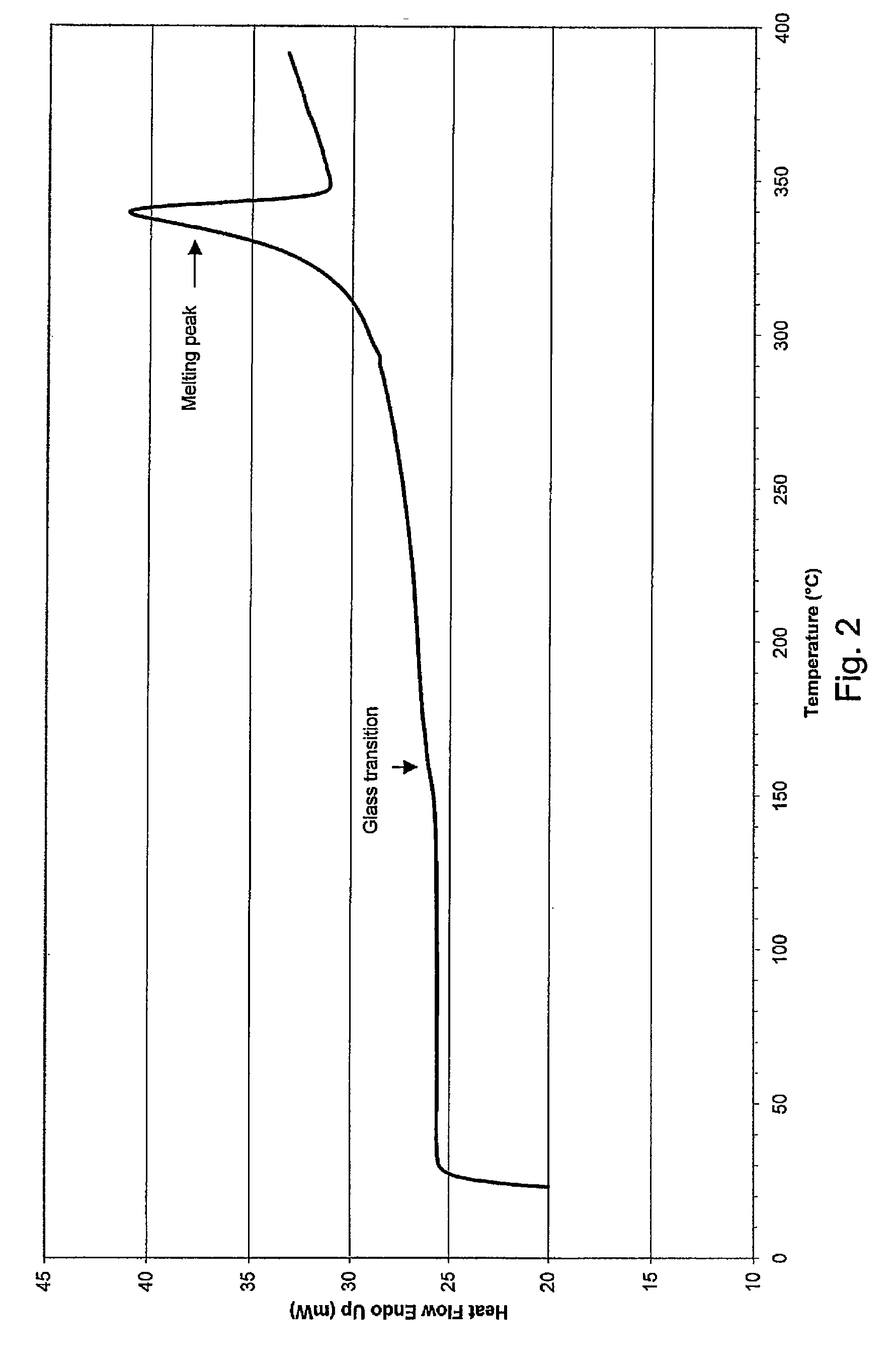
[0014] An advantage of the implant and method of the invention is that amorphous PAEK is suited to the manufacture of a firm implant into which a permanent deformation can be bent in situ.
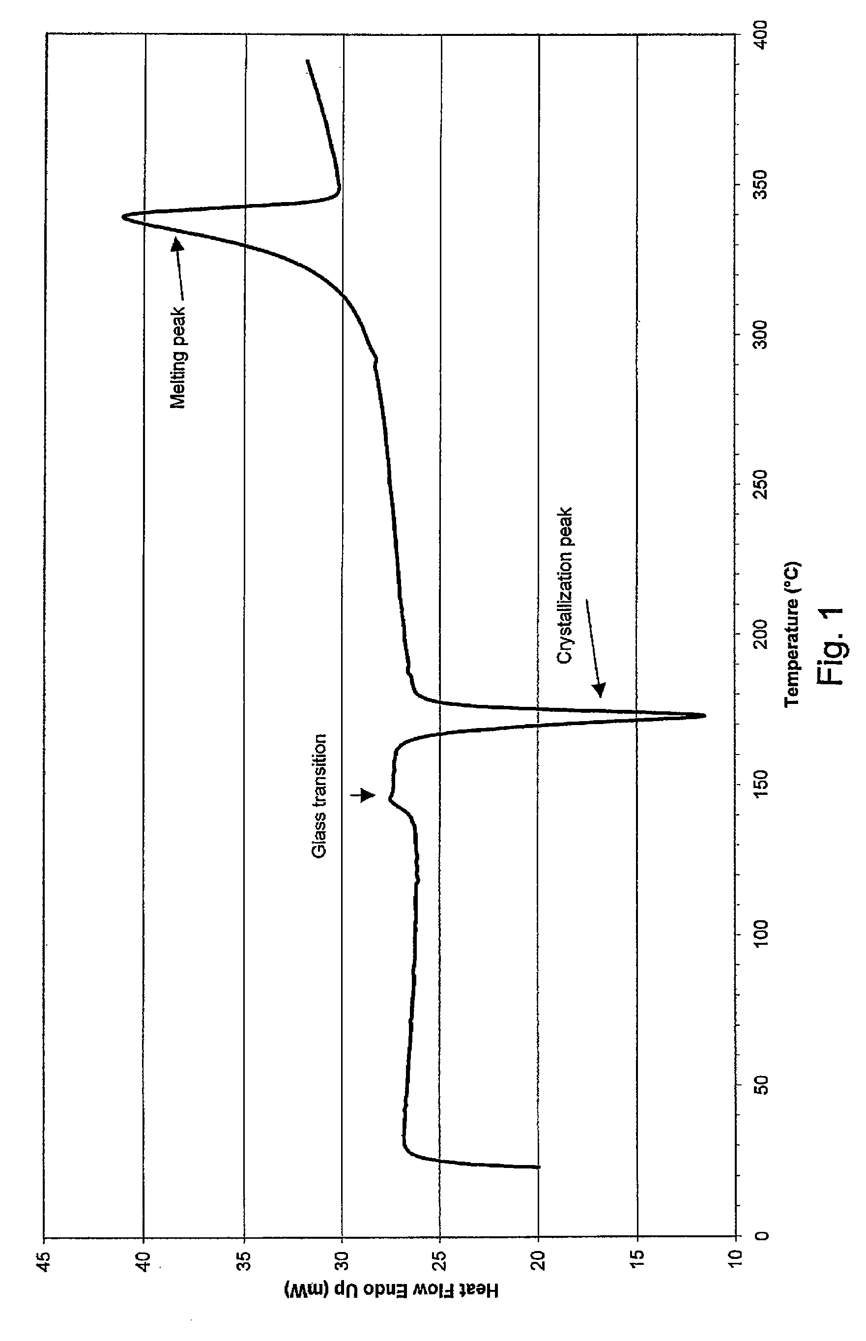
[0015] Further, the idea of an embodiment of the invention is that PAEK has an inhomogeneous form such that a second section of the body comprises the same polyaryletherketone as the first section but has a crystallization peak in its DSC-curve. An advantage is that the implant is stronger than an implant of the same design but comprising only amorphous PAEK, and has a higher elongation at break than an implant comprising only crystalline PAEK.
[0016] Further, the idea of an embodiment of the invention is that in the method the cooling rate of the body is controlled in such a manner that the PAEK present in section(s) of the body having smaller cross-sectional areas cools in an amorphous state, and the PAEK present in section(s) of the body having larger cross-sectional areas cools in a crystalline state, or that the implant is formed in a mould that has two or more sections and wherein at least one section is at a lower temperature than another section. An advantage is that the method can be carried out with normal processing steps of injection moulding, extrusion or compression moulding without any additional processing steps.

Problems solved by technology

In an X-ray image, the intensive shadow produced by a metal implant overlaps the very area important to the surgeon, making it difficult, or sometimes even impossible, to adequately gain information for judging the state of the tissue.
One of the problems associated with bio-stable implants made of highly crystalline polymers, such as polyaryletherketones, is that they are difficult to shape in situ into the required shape.

Method used


Image

  • Surgical implant and manufacturing method
  • Surgical implant and manufacturing method
  • Surgical implant and manufacturing method

Examples


example 1

[0044] Regular sized dog-bone shaped tensile test specimens were produced using conventional injection moulding techniques. The length of the specimens were 100 mm, thickness 1.2 mm and width 10.5 mm. Pellets of PEEK-OPTIMA® LT1 and PEEK-OPTIMA® LT3 polymers were obtained from Invibio Ltd, of Thornton Cleveleys, England. Prior to injection moulding, the raw materials were dried at 120° C. for 10 hours to remove residual moisture.

[0045] The test specimens were moulded with a generally known Kraus-Maffei KM50C2 electro-hydraulic injection moulding machine. Barrel temperatures were between 355 and 375° C. for both PEEK-OPTIMA® LT1 and PEEK-OPTIMA® LT3 materials.

[0046] Mould temperature was 55° C. for PEEK-OPTIMA® LT1 material and 40° C. for the more easily flowing PEEK-OPTIMA® LT3 material. In other words, the mould temperature was substantially lower than the glass transition temperature Tg of the material to be processed. This resulted in rapid cooling and solidification of the mat...

example 2

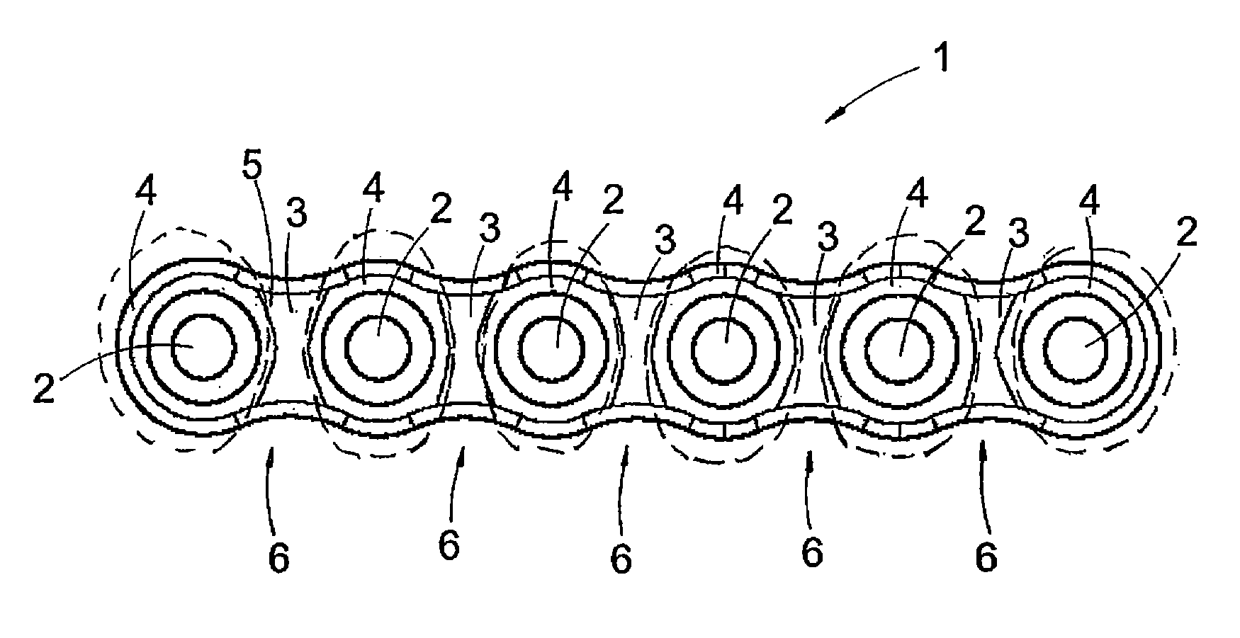
[0065] The plate 1 according to FIG. 3 was made from the material PEEK-OPTIMA® LT3 by first injection moulding the entire amorphous semi-finished product in the shape of plate 1 by using the manufacturing parameters and injection moulding devices presented in Example 1. Thus, the temperature of the mould was so low that PEEK hardened in an amorphous state.

[0066] Next, the amorphous semi-finished product, removed from the mould, was adapted into a heat treatment device comprising heating heads to be heated to a high temperature. Each heating head comprised a contact surface shaped in the shape of the part of the semi-finished product to be heated with said heating head. The heating heads were manufactured from an electrically conductive metal, the heating itself being implemented with electric resistances. The heating heads were pushed against the sites of the semi-finished product to be crystallized and hold in this position approximately 10 to 30 sec. In this case, the sites to be...

example 3

[0072] The cable tie according to FIG. 6, or any other implant having a shape comprising parts / sections having substantially different cooling rates, for example a fixation plate having thick sections of material around the fixing holes, can be manufactured for instance by injection moulding in such a manner that PAEK is injected into an isothermal mould. Since the ratio of the outer area of the lock 9 to its volume is substantially larger than the corresponding ratio in the band 10, the material constituting the lock 9 cools substantially slower than the material constituting the band 10. For this reason, the material constituting the lock 9 has more time to orientate into a crystalline state, as a result of which the lock 9 of the cable tie, cooled to room temperature, is composed of crystalline PAEK. In contrast, the band 10 cools very rapidly, owing to which the band 10 of the cable tie, cooled to room temperature, is composed of amorphous PAEK.

[0073] The cable tie according to...


PUM

PropertyMeasurementUnit
degree of crystallinityaaaaaaaaaa

Abstract

A surgical implant and a method for manufacturing the same. The surgical implant has a body comprising polyaryletherketone (PAEK). Said polyaryletherketone is a homopolymer and a first section of the body comprises a polyaryletherketone that has a crystallization peak in its DSC-curve.

Description

RELATED APPLICATION [0001] This application claims priority from European patent application number 06100802.5, filed Jan. 25, 2006, which is hereby incorporated herein by reference in its entirety for all purposes. FIELD OF THE INVENTION [0002] The invention relates to a surgical implant having a body comprising polyaryletherketone (PAEK). [0003] Further, the invention relates to a method for manufacturing a surgical implant, the implant having a body comprising polyaryletherketone (PAEK). BACKGROUND OF THE INVENTION [0004] Various artificial implants that can be implanted in the organ system are known. Herein, the concept ‘implant’ refers to shaped pieces to be implanted in the organ system, such as membranes, fixation plates, other three-dimensional spatial pieces, fixing means, such as screws, pins, rivets, tacks, and the like, that are used to support or attach tissue or to separate tissue from other tissue while healing. [0005] The implants can be made of biodegradable or bio-...

Claims


Application Information

Patent Timeline
Patent Type & Authority Applications(United States)
IPC IPC(8): A61F2/30
CPCA61L31/06A61L31/14C08L71/00B29C71/0063B29C71/02B29C2071/022B29K2995/0041A61B17/58A61B17/64A61F2/00A61F2/28
Inventor POHJONEN, TIMOLINDGREN, TOTTIPUHAKKA, TONIHAPPONEN, HARRIKAIKKONEN, AUVO
Owner INION
Learn More