Gate drive circuit
a drive circuit and gate technology, applied in pulse manipulation, pulse technique, instruments, etc., can solve the problems of large dispersion of voltage-sharing, increased element loss, excessive loss during, etc., and achieve the effect of suppressing the increase of switching element loss
- Summary
- Abstract
- Description
- Claims
- Application Information
AI Technical Summary
Benefits of technology
Problems solved by technology
Method used
Image

Examples
first embodiment
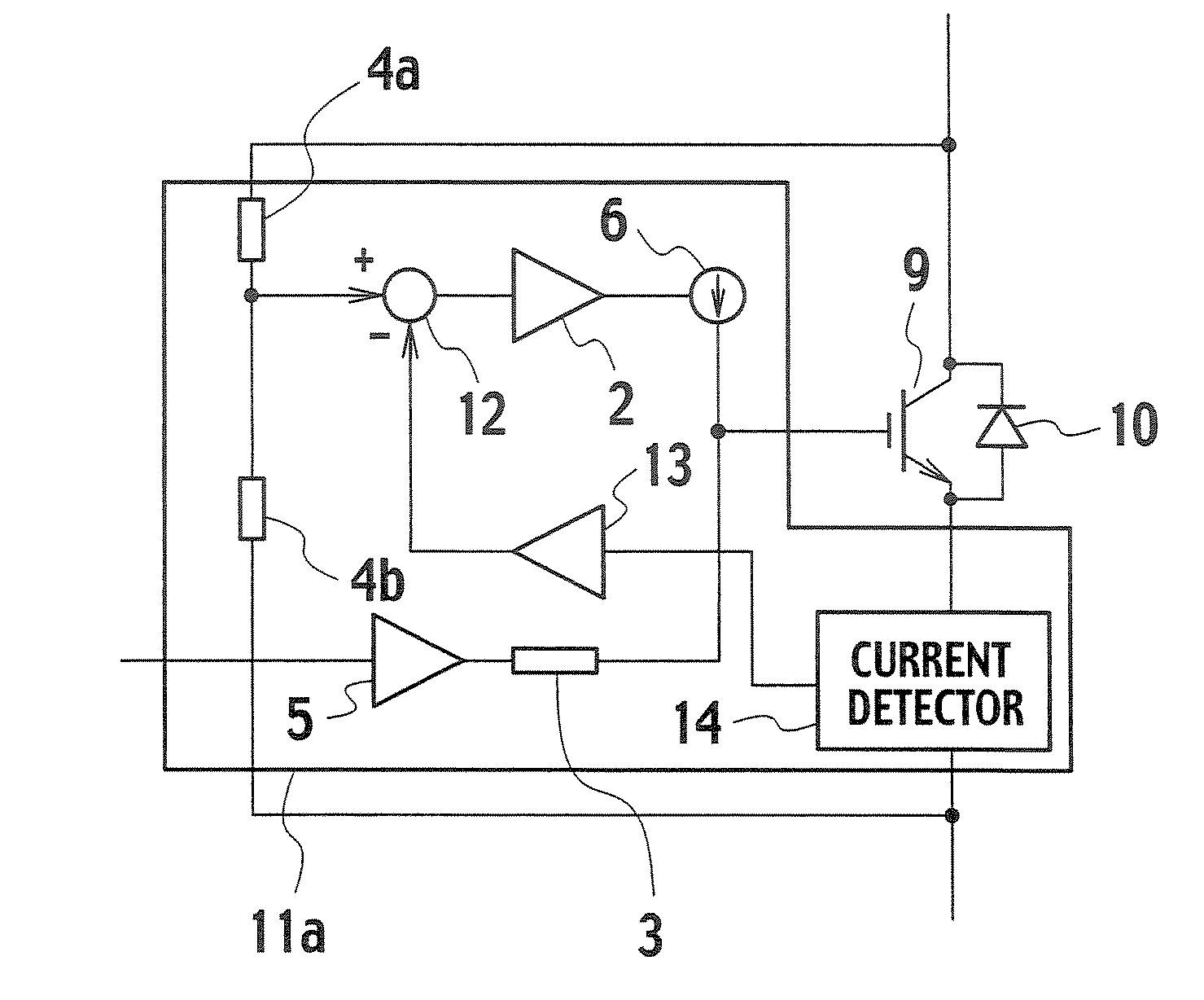
[0029]FIG. 4 is a circuit configuration diagram of a gate drive circuit of a first embodiment. A gate drive circuit 11a drives a switching element 9. The gate drive circuit 11a has a voltage amplifier 13, an adder 12, and a current detector 14 in addition to the configuration of FIG. 1.
[0030]The current detector 14 corresponds to a main current detection unit of the present invention, and one end thereof is connected to an emitter of the switching element 9. The current detector 14 detects a collector current flowing through the switching element 9, and outputs a voltage, which is proportional to the detected current, to the voltage amplifier 13. The voltage amplifier 13 amplifies the voltage outputted from the current detector 14, and outputs the resultant voltage to an inverting input terminal of the adder 12.
[0031]Resistors 4a and 4b for dividing a voltage are connected to each other in series between a collector of the switching element 9 and the other end of the current detecto...
second embodiment
[0038]FIG. 5 is a circuit configuration diagram of a gate drive circuit of a second embodiment. With the configuration of the first embodiment, the collector current of the switching element 9 is directly detected by the current detector 14. However, there is a case where a current detector is often expensive, and where the size thereof is large. In the configuration of the gate drive circuit of the second embodiment shown in FIG. 5, a collector current is indirectly detected by a gate voltage of the switching element 9, in place of the current detector 14.
[0039]A gate electrode of the switching element 9 corresponds to gate voltage detection unit of the present invention, and is connected to an input of a voltage amplifier 13. The voltage amplifier 13 amplifies a gate voltage of the switching element 9, and outputs the resultant voltage to an inverting input terminal of an adder 12.
[0040]Next, operations of the second embodiment configured as described above will be described. The ...
third embodiment
[0042]The gate drive circuit of the second embodiment indirectly detects the collector current of the switching element 9 with a gate voltage. However, in a number of large electrical power elements, a gate voltage takes a value in a relatively wider range of +15V to −15V. For this reason, there is a case where a somewhat complicated electronic circuit is needed in order to detect a gate voltage. In contrast, in a gate drive circuit of a third embodiment shown in FIG. 6, a gate voltage is not directly used. Instead, a collector current is indirectly detected based on a current flowing through a gate resistor.
[0043]A current detector 15 corresponds to gate current detection unit of the present invention, and one end thereof is connected to a gate terminal of a switching element 9 through a gate resistor 3. The other end of the current detector 15 is connected to an output terminal of a voltage amplifier 5. With this, the current detector 15 outputs a voltage, which is proportional to...
PUM
 Abstract
Description
Claims
Application Information
 - R&D
- Intellectual Property
- Life Sciences
- Materials
- Tech Scout
- Unparalleled Data Quality
- Higher Quality Content
- 60% Fewer Hallucinations
Browse by: Latest US Patents, China's latest patents, Technical Efficacy Thesaurus, Application Domain, Technology Topic, Popular Technical Reports.
© 2025 PatSnap. All rights reserved.Legal|Privacy policy|Modern Slavery Act Transparency Statement|Sitemap|About US| Contact US: help@patsnap.com